2022年4月12日星期二

How to use cat et Software

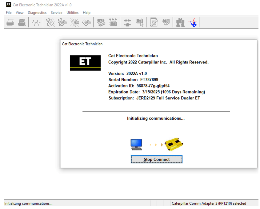
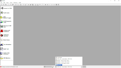
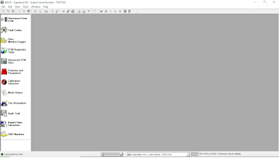
 Cat ET is cat electronic technician and this is the software that caterpillar produces for basically any other technicians or a customer to be able to communicate with their engine their machine and see what the codes are and see what the sensors are reading so certain diagnostic tests on it. This is software you have to use for cat equipment.

It does not work unless it is licensed the license determines what version of et basically you have. There are about 20 different licenses out there, there’s truck only there’s taps and military. Most common is dealer and customer version.

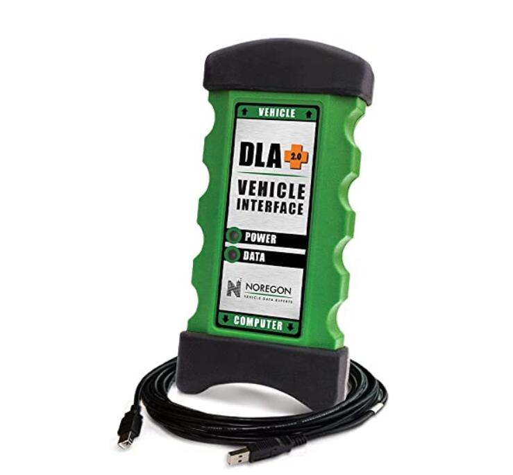
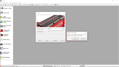
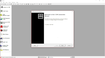
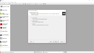
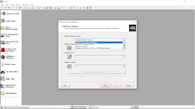
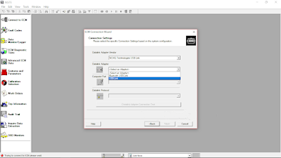
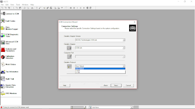
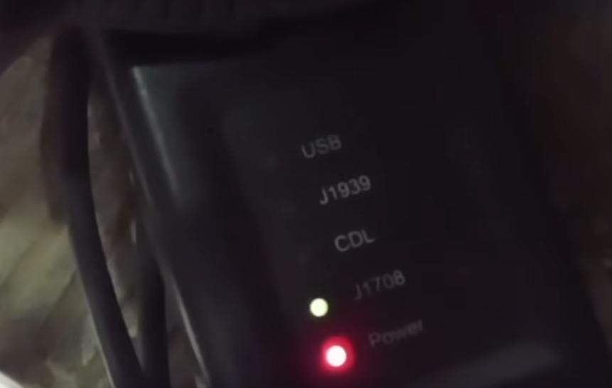
Et does not work by itself, need some sort of com adapter . if you plug into a truck you need a different adapter to go from the com adapter to truck. When you turn et on and it’s trying to communicate you should be getting at least one blinking light.

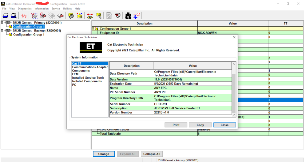
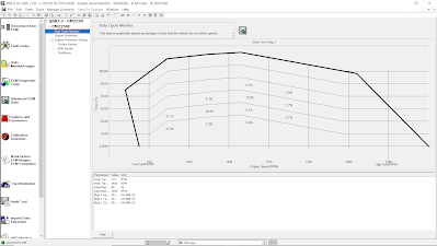
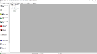
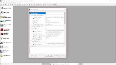
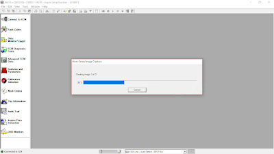
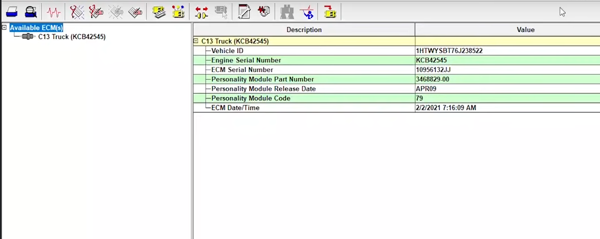
When you first connect below is the screen you going to get. This is basically a quick snapshot of info about your machine or engine. There are multiple control modules they are going to be displayed on the left this is a truck engine so long as one ecm displayed on the left. It giving some basic info like series number ecm date.

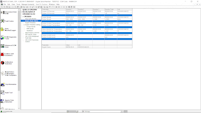
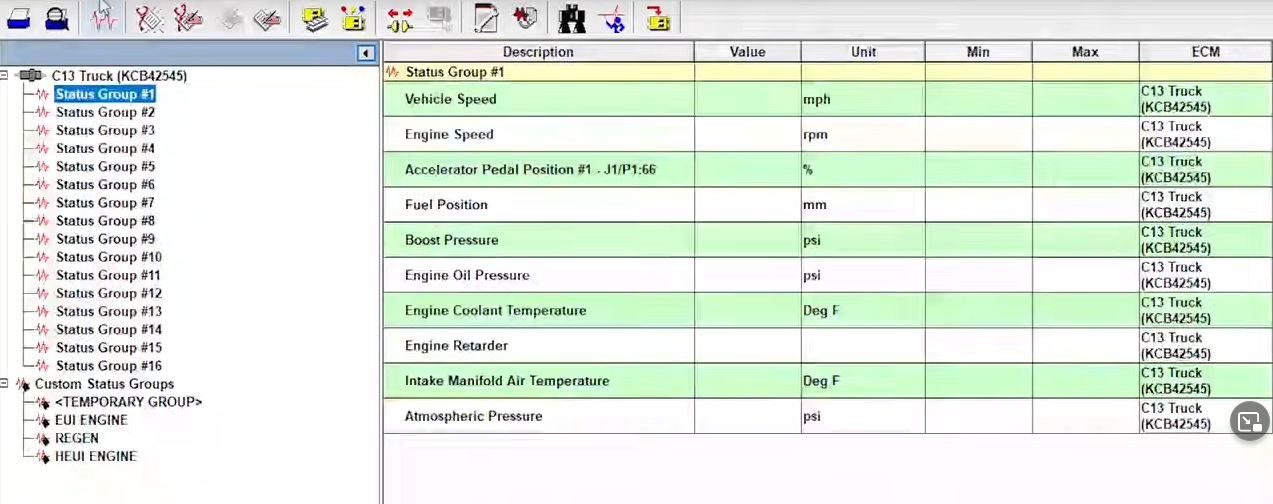
Then the status screen. The status screen will tell you what sensors are reading also will tell you inputs and outputs so if your exhaust break or your Jacobs break was set on it would show you what it’s set to if it’s reading properly. Such as the accelerator pedal position notice the min max as long as you on the screen it will keep the minimum and maximum, once you change screens though in the status screen to different status group it’s going to reset the minimum maximum from that previous screen and it will erase them forever. But it will now start recording mininum and maximum for the current screen.

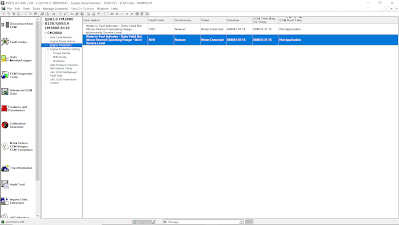
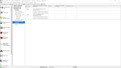
Diagnostic part displays trouble shooting codes if you click on that either in the logged or active events or diagnostic codes it going to take you to either something called component-based trouble shooting or going to try to log into sis which is cat’s service information system.

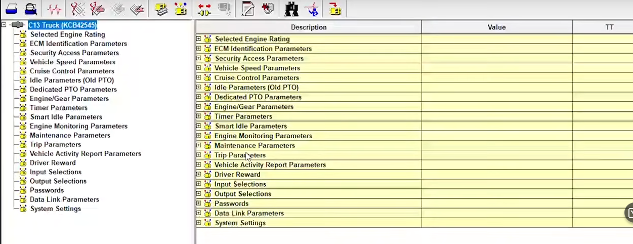
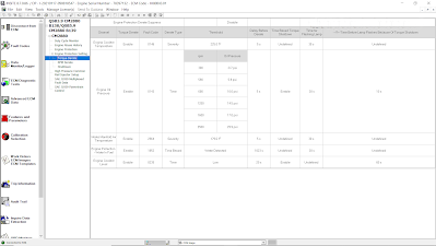
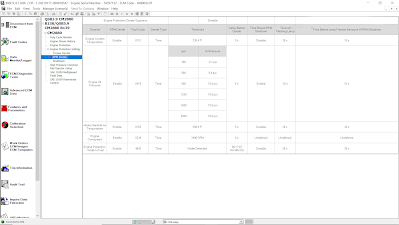
Configuration part will get easily messing stuff up if you do not know what you are doing. Take the vehicle speed limit for example, that is under vehicle speed parameters and it’s on the very top line there vehicle speed limit go up to 127 miles an hour however if you try to change it you may require factory password or a customer password .Under diagnostics there’s a lot of features


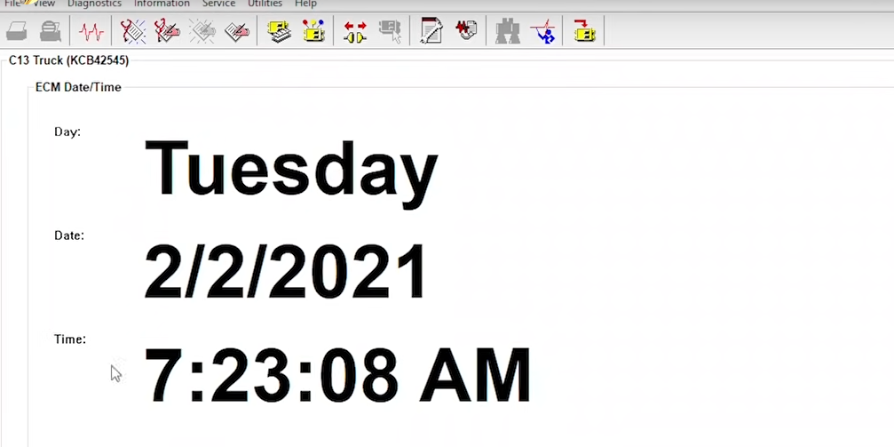
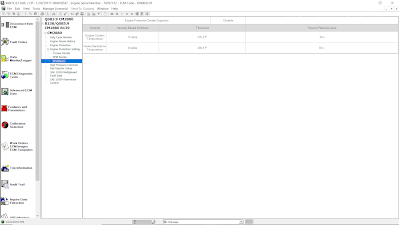
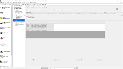
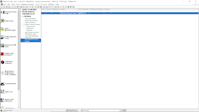
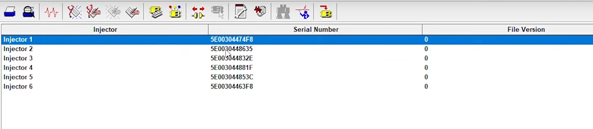
At service part you can change ECM date and time. This will enable you to change the ecm date and time a lot of the time it is not accurate. Calibration is where you do injector trim calibrations these are your injector trim files just like the fls and fts you should not be changing your injector trim files to just an arbitrary number they should match what is exactly on the injector those are there from the factory for a reason. To let the injectors in the engine run at optimal levels pls do not mess with your injector trim files leave them what they’re supposed to.


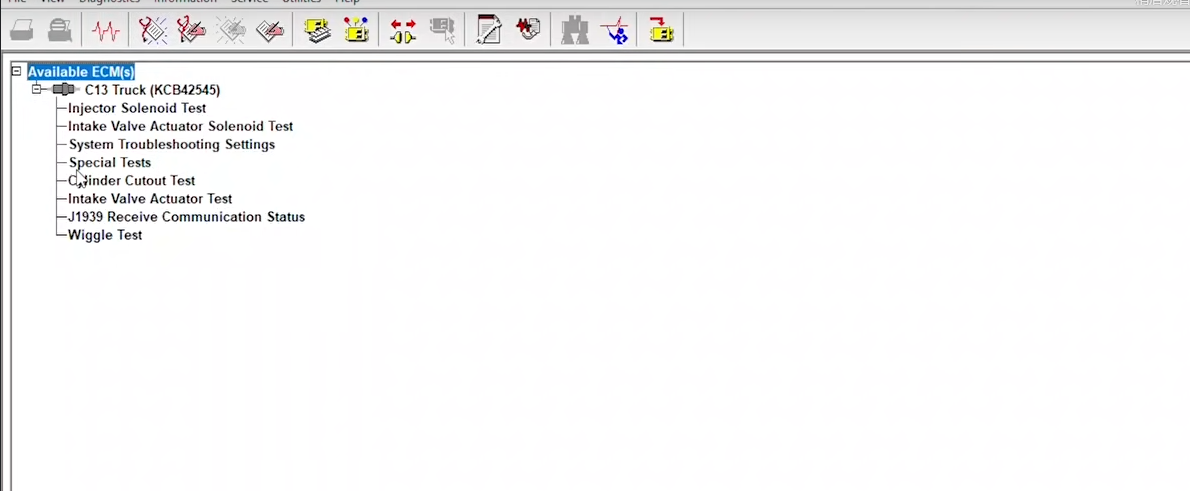
There is also trainer part would show you a bunch of different engines and machines you can click on the trainer mode and what it’s going to do is going to fake connect\ to one of these machines or engines. It going to let you do tests like a cylinder cutout test change parameters fake timing tests change configuration whatever you want to do you not hurting or break anything, or change a parameter not be able to change it back. because this is actual feature of Caterpillar ET Software. Pls use this if you unfamiliar with how to use et you will learn a lot.

The downside of the trainer is of course you’re not actually hooked up to a new engine so you’re not going to be able to do real troubleshooting where you can actually hear the engine running, hear a tone change when a cylinder cut out things. There is a lot of features to et for you to explore.

2022年4月11日星期一

Cat Caterpillar ET 2022A Electronic Technician Diagnostic Software Released

 Latest Version CAT Caterpillar ET 2022A Electronic Technician Diagnostic Software With 1 Time Free Activation

Note:
1.After receiving the payment, we will send you the software by email.
2. we will remote help customer installed and activation for a single PC by Teamviewer!


Diagnostic Software Caterpillar ET 2022A (replaces CAT ET 2021B, 2020C, 2019C) :
1.Latest Caterpillar ET 2022A Software to work with CAT/CAT3 Truck Scanner
2.With one free activation, can send software online
3.Support Multi-languages:English, Chinese, Danish, French, German, Italian, Japanese, Portuguese, Russian, Spanish
4. OS:Windows 7 32 bit, Windows 7 64 bit, Windows 8/8.1 32 bit, Windows 8/8.1 64 bit, Windows 10 32 bit, Windows 10 64 bit

PC, Communication Hardware, and Cable Requirements
To run the service tool, the next PC, communication hardware, and cable requirements must be met.
NOTE: The minimum PC Configurations should not be used as a standard when buying new personal computers for service tool purposes. If the existing equipment meets these minimum requirements, it will run the service tool.

PC Requirements
Recommended Configurations
PC containing a 2.0 GHz dual-core processor
3GB RAM
3GB of the available hard disk drive
DVD-ROM drive (optionally)
15.4-inch XGA Screen (1280x1024 compatible)
Microsoft Windows™ 7 Professional or Windows 8 Professional, Windows 10 Professional (Not tested with Home Edition) (Note: Windows 8 RT is not supported)
RS232 port with 16550AF UART or compatible (for use with Comm Adapter II)
USB 1.1 or 2.0 port (for use with Comm Adapter 3)
Ethernet RJ45 connector
Built-in pointing device or mouse
For security purposes, Microsoft Internet Explorer version 11 or newer or Microsoft Edge is recommended.
Note: The most recent version of Microsoft Internet Explorer may not be validated to work with the service tool.

Caterpillar electronic technician 2022A with WinFlash future is an updated version of the caterpillar dealer diagnostic software that can help technicians to diagnose existing and potential problems with their electronically controlled Caterpillar Engines and Machines.

To get the vehicle information the CAT ET Software must be connected to the Electronic Control Module (ECM). For this purpose, you need a suitable diagnostic link adapter (DLA), for instance, Genuine CAT Comm Adapter III .

The laptops with ARM CPUs (Snapdragon 8cx, Microsft SQ1, etc) type are not supported!

The list of supported CAT machines and engines can be found below:
Engines:
Electric Power
Electric Power Generation
Industrial
Marine Power Systems
Oil and Gas

Machines:
Articulated Trucks
Asphalt Pavers
Backhoe Loaders
Cold Planers
Compactors
Dozers
Drills
Excavators
Feller Bunchers
Forest Machines
Forwarders
Harvesters
Hydraulic Mining Shovels
Knuckleboom Loaders
Material Handlers
Motor Graders
Off-Highway Trucks
Pipelayers
Road Reclaimers
Site Prep Tractors
Skid Steer and Compact Track Loaders
Skidders
Telehandlers
Track Loaders
Underground - Hard Rock
Underground - Longwall
Underground - Room and Pillar
Utility Vehicles
Wheel Dozers
Wheel Excavators
Wheel Loaders
Wheel Tractor-Scrapers

What's New - 2022A
Microsoft® Windows™ 11 Compatibility

Service tool testing has been performed and the service tool is compatible with Windows 11.

ECM File Replacement Compare Feature

The service tool now has an ECM Replacement File Compare feature for troubleshooting purposes. This feature allows the user to compare one ECM replacement file with another from within the ECM Replacement feature screen. The feature will highlight the differences between the selected files as a whole or the user may select the “only show differences” checkbox.

Configuration Group Headings on ECM Replacement Feature

In order to help the user find ECM replacement configuration items easier, configuration items in the ECM Replacement, Fleet Configuration, and Product ECM features are now grouped under their group sub-headings, as is done in the main configuration feature.

What's New - 2021C
Feature Protection System Password Copy

The Feature Protection System (FPS) has a new "Easy Copy" link to copy passwords in a single operation. The service tool can automatically obtain the passwords from the clipboard and populate the FPS dialog. The service tool dialog also has a new "Easy Paste" button that allows the user to paste data of the correct format from the clipboard. Passwords can still be pasted using customary copy/paste operations, such as the context menu or the CTRL + V hotkey combination.

Screen Resolution Requirement Update

The minimum requirement for screen resolution has been updated to 1366x768, or at least 1366 pixels horizontally and at least 768 pixels vertically. The recommended screen resolution is at least 1600x1200. The service tool window displays with a minimum size of 1024x680.

What's New - 2021B
End of Support for Windows 8

Microsoft is ending extended support for Windows 8 as of January 2023. The service tool will be ending support for Windows 8 after the 2021C release.

Calibration Images

Images attached to calibration instructions will no longer need to be opened manually to be viewed by a technician. The service tool will now have split user interface windows for calibrations that display pictures. This will allow the technician to see the images without having to navigate away from the instructions. Images may be opened into individual windows and resized for better clarity. The user interface for calibrations that do not display pictures will remain unchanged.

Default PC Browser

The service tool will no longer automatically launch web pages in Microsoft Internet Explorer. Web pages will now launch in whatever application is configured as the default internet browser. Certain web pages require a specific browser and may launch in a different browser.

What's New - 2021A
No significant new features or feature enhancements

What's New - 2020C
No significant new features or feature enhancements

What's New - 2020B
Trainer Update – 299D3

The 299D3 Skid Steer Loader has been added to the Trainer application.

What's New - 2020A
Product Status Report Updates

The Product Status Report has been updated to include throttle configuration information.

Built-in Factory Password Generator

The experimental feature allows you to decode (18-Bit passwords not supported) factory passwords

What's New - 2019C
Indication of Selected Communications Adapter

The service tool now displays the selected communications adapter when the service tool is disconnected. The adapter name is displayed in the status area at the bottom right of the service tool window.

Communication Hardware
Caterpillar Communication Adapter III
Configuring Cat Electronic Technician to use the Communication Adapter 3
For Cat Electronic Technician to work with the Communication Adapter 3, the settings must be changed to select the Communication Adapter 3 as the Communication Interface Device:
Step 1 Start Cat Electronic Technician.
Step 2 Click the Stop Connect button when it appears.
Step 3 Select the Utilities menu.
Step 4 Choose “Preferences > Modify...”.
Step 5 Select the Communications tab.
Step 6 Select Cat Comm Adapter 3 (RP1210) and click OK.
NOTE: Because a growing number of products require multiple data link service, the “Enable Dual Datalink Service” checkbox has been pre-selected.
Servicing ECMs on more than one data link requires this check box to be enabled.
Failure to do this will result in undetected ECMs and reduced functionality.

Package Includes:
1pc x Caterpillar ET 2022A software (Can choose to send online)

2022年2月10日星期四

Why to buy JPRO professional heavy-duty truck scan tool


JPRO Professional heavy duty truck scan tool is an easy to use diagnostic tool that can help you establish the possible problem. You will be surprised how this scan tool goes more in-depth and takes diagnosis to the next level.

It is a simple yet most comprehensive and powerful diagnostic tool that is compatible with all models. Besides, JPRO Professional heavy duty truck scan tool provides complete and real-time diagnostic services. It is also uniquely designed to provide a repair solution for the diagnosed problem, and better yet, is equipped with bi-directional functionality.

This scan tool is so useful that you can fully diagnose your car without leaving your garage. And as such, when you want a hustle-free car diagnosis, then JPRO Professional heavy duty truck scan tool is a must-have diagnosis device.

Detailed review of JPRO Professional
Compatibility

There is good news for you! JPRO Professional heavy duty truck scan tool is compatible with all car models and types. It can see the entire car in a single pass on one screen. Astonishing, isn’t it?

It can diagnose all problems in medium-duty diagnose and heavy-duty modules such as:

Mack
Cummins
Volvo
And PACCAR

Equally, JPRO Professional heavy duty truck scan tool works well with medium models such as:

Isuzu
GM
Ford
And Sprinter

The most exciting part of this diagnostic tool is that you can perform parameter changes.

Also, DPF Regens and bi-directional tests can be effectively performed using the JPRO Professional heavy truck scan tool to obtain reliable data and faults.

As if that is not enough, it can effectively run in the latest windows and is compatible with iOS, Android devices. You can run this scanner with Windows 8 upwards but not any other lower version windows. Therefore if you are using macOS 10, you are ready to go with the latest version of the JPRO Professional heavy-duty truck scan tool.

Finally, Interestingly enough JPRO Professional heavy-duty truck scan tool runs on all android devices, and believe it or not, you can get a reading on your phone.

Display

You agree with me that a clear and simplified display forms the basis for quickly detecting a bug in your car.

Why-to-buy-JPRO-professional-heavy-duty-truck-scan-tool

Luckily, JPRO Professional heavy duty truck scan tool is user-friendly with an exceptional display system. If you own a heavy-duty truck or a mechanic, you can read and diagnose the entire truck in under one minute with just a single pass.

In just one screen, you will be able to get over 44,000 OE level fault codes as well as detailed repair information.

You do not have to be a technician to interpret the displayed information. JPRO Professional heavy duty truck scan tool displays information in an easy-to-understand graphical interface with all the vehicle systems comprehensively listed.

Therefore, it means that heavy-duty truck owners and mechanics can quickly read and make a diagnosis using JPRO Professional heavy-duty truck scan tool.

The toolbox allows you to check the entire health of your vehicles and view and print logo files. Other reports that you can view and print include LOV reports and Trip reports.

Besides, the JPRO Professional heavy-duty truck scan tool can store and record data for playbacks even when not connected to your track.
Software

JPRO Professional heavy duty truck scan tool uses the most comprehensive diagnostic software you can find on the market today.

The powerful software uses enhanced OEM fault-code information with ACM resets and cylinder cut-outs capabilities.

Moreover, it has an inbuilt Next Step Services Information that helps speed up the time taken to repair a truck.

As a result, you will be able to access digital photos, complete wiring, and installation information. Finally, it comes with a troubleshooting guide that makes diagnosis a no-brainer task.
Features and functionalities

JPRO Professional heavy-duty truck scan tool is a number one trusted scan tool by most car technicians. Do you want to know why? The secret is in what it can do.

Here a comprehensive look at the features.
1. Bi-directional controls

It is capable of performing parameter changes for Volvo and Mack.

Equally, JPRO Professional heavy-duty truck scan tool can perform DPF Regens for Detroit Diesel, Cummins, Volvo, Mack, and Internationals.

All these tests are bi-directional with proprietary faults and data.

2. OE level fault code information

Display 99% for both medium-duty and heavy-duty fault codes with a comprehensive OEM level component as well as the trailer descriptions.

3. Include heavy and medium-duty modules

Heavy-duty modules include PACCAR, international, Detroit Diesel, Cummins, Volvo, and Mack. The medium-duty modules include sprinter, Isuzu, GM, and Ford.

4. Fault management

It is capable of clearing faults as well as making a quick diagnosis with easy to use application.

5. Vehicle reporting

With the JPRO Professional scan tool, you can view and subsequently print logo files comprising LOV reports, Trip Reports, and Vehicle Health.

6. Store and save data

Effectively record all the data log files with playback capabilities even when not connected to the truck.

7. Comprehensive vehicle health status

In a single pass, you can be able to see the entire vehicle.

8. JPRO professional user diagnostic software

It has powerful software, a DLA 2.0 adapter, and the Panasonic Toughbook for enhanced diagnosis.

9. Ease of use and compatibility

It has 9-pin Heavy-Duty Cable, OBDII Cables, 6-pin Heavy-Duty Cable, and USB Cable.

2022年2月7日星期一

How to remove and install fuel transfer pump for Perkins

Here is a illustration for how to remove and install fuel transfer pump for Perkins 400A and 400D industrial engine.

Related Contents:
Newest Perkins EST 2020A & 2019A Full Support Free Download
Perkins SPI2 2018A EPC+Service Manual Free Download

Electrical Fuel Transfer Pump

Removal Procedure

NOTICE:Care must be taken to ensure that fluids are contained during performance of inspection, maintenance,testing, adjusting and repair of the product.Be prepared to collect the fluid with suitable containers before opening any compartment or disassembling any component containing fluids.

Dispose of all fluids according to local regulations and mandates.

Keep all parts clean from contaminants.

Contaminants may cause rapid wear and shortened component life.

Note: Put identification marks on all hoses, on all hose assemblies, on wires and on all tube assemblies for installation purposes. Plug all hose assemblies and tube assemblies. This helps to

prevent fluid loss and this helps to keep contaminants from entering the system.

1.Turn the fuel supply to the OFF position.

2.Turn the battery disconnect switch to the OFF position.

How-to-remove-and-install-fuel-transfer-pump-for-Perkins-1

3.Disconnect harness assembly (1).

4.Loosen hose clamps (4) and (5). Disconnect hoses (6) and (7).

5.Remove bolts (2) and remove electric transfer pump (3).

Installation Procedure

1.Ensure that the electric transfer pump is clean and free from damage. If necessary, replace the electric transfer pump.

How-to-remove-and-install-fuel-transfer-pump-for-Perkins-2

2.Position electric transfer pump (3) on the mounting and install bolts (2).

3.Tighten bolts (2) to a torque of 9 N·m (79 lb in).

4.Connect hoses (6) and (7). Tighten hose clamps (4) and (5).

5.Connect harness assembly (1).

6.Turn the fuel supply to the ON position.

7.Turn the battery disconnect switch to the ON position.

8.Remove the air from the fuel system.

Mechanical Fuel Transfer Pump

Removal Procedure

NOTICE:Do not allow dirt to enter the fuel system. Thoroughly clean the area around a fuel system component that will be disconnected. Fit a suitable cover over disconnected fuel system component.

NOTICE:Care must be taken to ensure that fluids are contained during performance of inspection, maintenance,testing, adjusting and repair of the product.

Be prepared to collect the fluid with suitable containers before opening any compartment or disassembling any component containing fluids.

Dispose of all fluids according to local regulations and mandates.

NOTICE:Keep all parts clean from contaminants.

Contaminants may cause rapid wear and shortened component life.

Note: Place identification marks on all hoses for installation purposes. Plug all hoses and all the ports in the fuel transfer pump. This helps prevent fluid loss, and this helps to keep contaminants from entering the system.

1.Turn the fuel supply to the OFF position.

How-to-remove-and-install-fuel-transfer-pump-for-Perkins-3

Note:The fuel transfer pump can be oriented in two positions. Before removing the fuel transfer pump from the cylinder block, note the orientation of flange (5) on fuel transfer pump (1) for assembly.

2.Loosen the hose clamps and disconnect the hoses (not shown) from fuel transfer pump (1).

3.Evenly loosen bolts (4) and remove fuel transfer pump (1) from the cylinder block.

Note:In order to remove the fuel transfer pump, it may be necessary to rotate the crankshaft until the operating plunger of the fuel transfer pump is not under pressure.

4.Remove O-ring seal (3) from fuel transfer pump (1).

Installation Procedure

NOTICE:Keep all parts clean from contaminants.Contaminants may cause rapid wear and shortened component life.

How-to-remove-and-install-fuel-transfer-pump-for-Perkins-4

1.Clean the mating surfaces of the cylinder block and flange (5) on the fuel transfer pump.

Note: Ensure that the camshaft lobe for the fuel transfer pump is at minimum lift before the fuel transfer pump is installed. The fuel transfer pump can be oriented in two positions. Ensure that the fuel transfer pump is oriented in the correct position.

2.Install a new O-ring seal (3) to fuel transfer pump (1).

3.Lubricate the operating plunger of fuel transfer pump (1) with clean engine oil.

4.Position fuel transfer pump (1) on the cylinder block. Ensure that the operating plunger is positioned correctly on the camshaft lobe. Install bolts (4). Tighten the bolts to a torque of 6 N·m (53 lb in).

5.Connect the hoses (not shown) to fuel transfer pump (1). Tighten the hose clamps.

Note: The inlet for the fuel transfer pump can be rotated 360 degrees by loosening bolt (2). The fuel inlet is adjustable in 15 degree increments. If adjustment is made to the position of the fuel inlet,tighten bolt (2) to a torque of 2.5 N·m (22 lb in).

6.Turn the fuel supply to the ON position.

7.Prime the fuel system. Refer to Systems Operation, Testing and Adjusting, “Fuel System -Prime” for additional information.

More Perkins EST,please refer to:Perkins Engine Trouble Repair

2022年2月1日星期二

How to Installation Mercedes Benz star diagnostic tool software

How to Installation Mercedes_Benz star diagnostic tool software

OS: Windows 10 Professional Edition 64 bit, The remaining space of the C drive is more than 300 G, and the memory is more than 4G. It is recommended to use an SSD hard disk。

1.Download the xentry IOS file and double-click it after decompression Star.exe

“Start” and select “Run as administrator”

How-to-Installation-Mercedes_Benz-star-diagnostic-tool-software-1

2.Then select the desired language and confirm installation of the following packages by clicking on “Install”:

How-to-Installation-Mercedes_Benz-star-diagnostic-tool-software-2

3.The InstallShield Wizard opens. Click “Next” to go to the general terms and conditions. Please accept them and click on “Next”:

How-to-Installation-Mercedes_Benz-star-diagnostic-tool-software-3

4.Destination folder: Confirm the predefined destination directory for XENTRY Diagnosis or enter a folder of your choice (if possible, the suggested path should be retained):

How-to-Installation-Mercedes_Benz-star-diagnostic-tool-software-4

5.Then click on “Next” to go to the installation window. Installation: To install, click the button with the same name as soon as the assistant for the installation of the program is ready. The installation process takes some time:

How-to-Installation-Mercedes_Benz-star-diagnostic-tool-software-5

6.After a successful installation click “Finish” to confirm: Then restart the system.After restarting your computer, this Hardware Selection Window will open: You can operate Open Shell either with XENTRY Diagnosis VCI or SDconnect. Please select the corresponding field for the hardware you are using. Note: This window appears whenever you start ConfigAssist and after installing updates.

7.After selecting the hardware a welcome window will be displayed if you go onto the button „Configure”. Please click onto “Continue” in the lower right corner.

How-to-Installation-Mercedes_Benz-star-diagnostic-tool-software-7

8.In the next window you can see information about product updates. Now click on “Next” until you come to “Install StartKey”. The system automatically searches for the latest StartKey on the StartKey server via the Internet connection. The StartKey is stored on the system.

How-to-Installation-Mercedes_Benz-star-diagnostic-tool-software-8
How-to-Installation-Mercedes_Benz-star-diagnostic-tool-software-9
How-to-Installation-Mercedes_Benz-star-diagnostic-tool-software-10

9.If you are not a Mercedes-Benz dealer, you need to use a patch to use this software.

How-to-Installation-Mercedes_Benz-star-diagnostic-tool-software-11
How-to-Installation-Mercedes_Benz-star-diagnostic-tool-software-12
How-to-Installation-Mercedes_Benz-star-diagnostic-tool-software-13

Set connect C4 IP address

How-to-Installation-Mercedes_Benz-star-diagnostic-tool-software-14

10.If you use C6 connection, VCI is required when registering, and use USB or WIFI to connect to the computer.

2022年1月30日星期日

ADVANCED ECM DATA ON CUMMINS INSITE SOFTWARE (CUMMINS ENGINES)

Advanced ECM Data on Cummins INSITE Software (CUMMINS Engines)

Advanced ECM Data
Advanced-ECM-Data-on-Cummins-INSITE-Software-1

To open the Advanced ECM Data:
1). Connect diagnostic adapter tool (Nexiq USB-Link) to diagnostic port on Cummins Engine or ECM Image. Read More: How to Connecting CUMMINS Engines using Cummins INSITE Software.
2). Click Advanced ECM Data on the Viewbar, as Figure 1.2 below.
Advanced-ECM-Data-on-Cummins-INSITE-Software-2

(A). Duty Cycle Monitor
The “Duty Cycle Monitor” graphically displays percentages of time that the vehicle has run within specific operating ranges. Operating ranges are based on engine speed (rpm) vs torque. Engine speed displays on the X axis and torque displays on the Y axis of the graph. The values for rpm and torque are defined by the calibration. A bold line is displayed on the graph as a generic torque curve reference. This curve is the same across all engines.

Each block on the graph shows an intersection of rpm values and torque values that represent a specific operating range for the vehicle. The number displayed in each block is a percentage of the total time that the vehicle operated in that range. For example, if a graph has a total of 500 hours of operating time with 5% displayed in a block, then the vehicle spent 25 hours operating within that range.

The total of the percentages displayed in the graph may be a little more or less than 100%. This is due to rounding when INSITE™ reads the data from the ECM.

Three different Duty Cycle maps can be displayed in the Duty Cycle Monitor window:
a). Short Term Map 1 (as Figure 1.1 above).
This map logs a total of 500 hours. When 500 hours has elapsed, INSITE automatically begins logging on Short Term Map 2.
b). Short Term Map 2.
This map logs a total of 500 hours. INSITE automatically begins logging on Short Term Map 2 after 500 hours have been logged on Short Term Map 1.
Advanced-ECM-Data-on-Cummins-INSITE-Software-3
c). Long Term Map.
This map records operating ranges over the file of the engine or vehicle. It can not be reset.
Advanced-ECM-Data-on-Cummins-INSITE-Software-4
Note: The parameter values will vary depending on which map is displayed.
→Time Remaining – the amount of time remaining for the displayed map. The Short Term Maps last for 500 hours, and the Long Term Map is practically infinite.
→Map Start Time – the ECM time when logging began for the currently selected map.
→Advertised Power RPM – the engine speed at which the power peak is achieved.
→Advertised Power at RPM – the maximum horsepower rating for this engine.
→Replace Torque RPM – the engine speed at which peak torque is achieved.
→Peak Torque at RPM – the maximum engine power supported by this engine.

(B). Engine Protection Setting
Engine Protection is designed to prevent engine damage when a sensor value exceeds a certain limit for critical engine operating parameters. The Engine Protection feature enables you to view the Engine Protection fault history associated with a specific Engine Protection fault.

A fault history log is provided for each Engine Protection parameter. The last five occurrences of each Engine Protection fault are displayed.

Torque Derate/ RPM Derate
Advanced-ECM-Data-on-Cummins-INSITE-Software-5
Advanced-ECM-Data-on-Cummins-INSITE-Software-6

(C). Engine Protection
Advanced-ECM-Data-on-Cummins-INSITE-Software-7
Advanced-ECM-Data-on-Cummins-INSITE-Software-8

(D). Engine Abuse History
The Engine Abuse History feature tracks the time the engine has been running above recommended values for various engine parameters. This provides comprehensive data about the life of the engine, how it has been used, how it has been maintained, and what abuse it may have been subjected to.
Advanced-ECM-Data-on-Cummins-INSITE-Software-9

(E). High Pressure Common Rail Injector Setup
This special feature is used to display and update the barcode values for each injector installed on the engine. The Injector Barcode is an alpha-numeric character sequence, physically marked on the injector. This barcode indicates the injector’s fueling characterization. The ECM uses this information to adjust the injection commands, improving fueling accuracy and minimizing injector-to-injector fueling variations. It is important to update this information when an injector or ECM is replaced. The manual procedure should be used when replacing an injector. The import procedure should be used when replacing or ROM booting an ECM.
Advanced-ECM-Data-on-Cummins-INSITE-Software-10

(F). SAE J1939 Multiplexed Fault Data
Advanced-ECM-Data-on-Cummins-INSITE-Software-11

(G). SAE J1939 Powertrain Control
SAE J1939 Powertrain Control enables on-board vehicle control devices such as Acceleration Slip Regulation (ASR) for traction control or electronically controlled transmissions to take control of the engine and/or engine subassemblies via the SAE J1939 datalink (network).

Use the SAE J1939 Powertrain Control feature to view a history of when the engine was controlled by a J1939 device. A record of attempts made to control the ECM through a J1939 device can be helpful during troubleshooting.
Advanced-ECM-Data-on-Cummins-INSITE-Software-12


2022年1月25日星期二

How to Connecting CUMMINS Engines using Cummins INSITE Software

How to Connecting CUMMINS Engines using Cummins INSITE Software

Cummins INSITE

How-to-Connecting-CUMMINS-Engines-using-Cummins-INSITE-Software-1

#To Connect to an ECM
1). Open Cummins INSITE through shortcut on desktop, using Status bar to select a connection options.

How-to-Connecting-CUMMINS-Engines-using-Cummins-INSITE-Software-2

2). Click the dropdown box on the Status bar to view a list of all currently available connection options, or click Add New to create one, then click Next.

How-to-Connecting-CUMMINS-Engines-using-Cummins-INSITE-Software-3

3). Use the ECM Connection Type page, and choose Datalink Adapter (Connect using a Datalink Adapter), then click Next.

How-to-Connecting-CUMMINS-Engines-using-Cummins-INSITE-Software-4

4). Select Connection Settings, Datalink Adapter Vendor, Datalink Adapter, and Datalink Protocol, then click Next.

How-to-Connecting-CUMMINS-Engines-using-Cummins-INSITE-Software-5
How-to-Connecting-CUMMINS-Engines-using-Cummins-INSITE-Software-6
How-to-Connecting-CUMMINS-Engines-using-Cummins-INSITE-Software-7

6). Click Connect to ECM.
→If you are connecting to a new ECM or an ECM without existing ECM passwords, select “None” in the Security Type: dropdown list.
→If you then want to define ECM security type passwords, select ECM Passwords on the Tools menu once connected to the ECM.

7). The Work Order Wizard is automatically displayed for you to create a work order for the selected connection, then click OK.
→You can disable the Wizard from starting automatically by unchecking the Enable Work Order Mode checkbox in the Work Orders page of the Options window. Read More: Work Orders on Cummins INSITE Software (CUMMINS Engines).

How-to-Connecting-CUMMINS-Engines-using-Cummins-INSITE-Software-8

8). Wait the Work Order/Image Creation until 100% of creating image.

How-to-Connecting-CUMMINS-Engines-using-Cummins-INSITE-Software-9
How-to-Connecting-CUMMINS-Engines-using-Cummins-INSITE-Software-10