Here is a illustration for how to remove and install fuel transfer pump for Perkins 400A and 400D industrial engine.
Related Contents:
Newest Perkins EST 2020A & 2019A Full Support Free Download
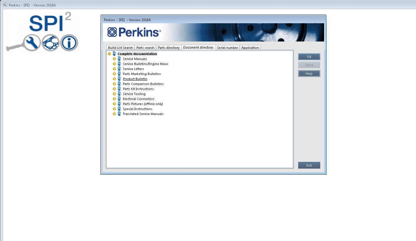
Perkins SPI2 2018A EPC+Service Manual Free Download
Electrical Fuel Transfer Pump
Removal Procedure
NOTICE:Care must be taken to ensure that fluids are contained during performance of inspection, maintenance,testing, adjusting and repair of the product.Be prepared to collect the fluid with suitable containers before opening any compartment or disassembling any component containing fluids.
Dispose of all fluids according to local regulations and mandates.
Keep all parts clean from contaminants.
Contaminants may cause rapid wear and shortened component life.
Note: Put identification marks on all hoses, on all hose assemblies, on wires and on all tube assemblies for installation purposes. Plug all hose assemblies and tube assemblies. This helps to
prevent fluid loss and this helps to keep contaminants from entering the system.
1.Turn the fuel supply to the OFF position.
2.Turn the battery disconnect switch to the OFF position.
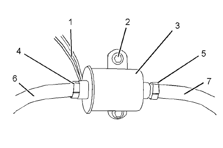
3.Disconnect harness assembly (1).
4.Loosen hose clamps (4) and (5). Disconnect hoses (6) and (7).
5.Remove bolts (2) and remove electric transfer pump (3).
Installation Procedure
1.Ensure that the electric transfer pump is clean and free from damage. If necessary, replace the electric transfer pump.

2.Position electric transfer pump (3) on the mounting and install bolts (2).
3.Tighten bolts (2) to a torque of 9 N·m (79 lb in).
4.Connect hoses (6) and (7). Tighten hose clamps (4) and (5).
5.Connect harness assembly (1).
6.Turn the fuel supply to the ON position.
7.Turn the battery disconnect switch to the ON position.
8.Remove the air from the fuel system.
Mechanical Fuel Transfer Pump
Removal Procedure
NOTICE:Do not allow dirt to enter the fuel system. Thoroughly clean the area around a fuel system component that will be disconnected. Fit a suitable cover over disconnected fuel system component.
NOTICE:Care must be taken to ensure that fluids are contained during performance of inspection, maintenance,testing, adjusting and repair of the product.
Be prepared to collect the fluid with suitable containers before opening any compartment or disassembling any component containing fluids.
Dispose of all fluids according to local regulations and mandates.
NOTICE:Keep all parts clean from contaminants.
Contaminants may cause rapid wear and shortened component life.
Note: Place identification marks on all hoses for installation purposes. Plug all hoses and all the ports in the fuel transfer pump. This helps prevent fluid loss, and this helps to keep contaminants from entering the system.
1.Turn the fuel supply to the OFF position.
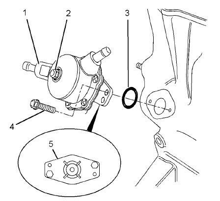
Note:The fuel transfer pump can be oriented in two positions. Before removing the fuel transfer pump from the cylinder block, note the orientation of flange (5) on fuel transfer pump (1) for assembly.
2.Loosen the hose clamps and disconnect the hoses (not shown) from fuel transfer pump (1).
3.Evenly loosen bolts (4) and remove fuel transfer pump (1) from the cylinder block.
Note:In order to remove the fuel transfer pump, it may be necessary to rotate the crankshaft until the operating plunger of the fuel transfer pump is not under pressure.
4.Remove O-ring seal (3) from fuel transfer pump (1).
Installation Procedure
NOTICE:Keep all parts clean from contaminants.Contaminants may cause rapid wear and shortened component life.
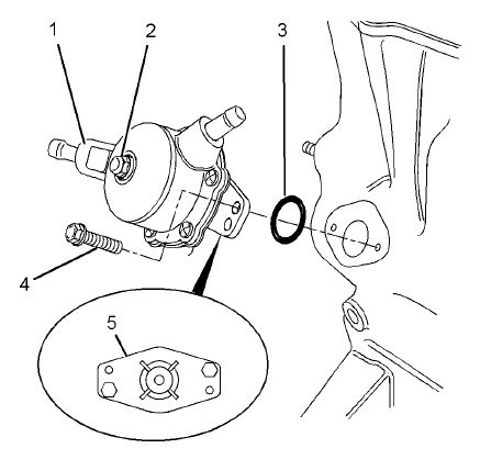
1.Clean the mating surfaces of the cylinder block and flange (5) on the fuel transfer pump.
Note: Ensure that the camshaft lobe for the fuel transfer pump is at minimum lift before the fuel transfer pump is installed. The fuel transfer pump can be oriented in two positions. Ensure that the fuel transfer pump is oriented in the correct position.
2.Install a new O-ring seal (3) to fuel transfer pump (1).
3.Lubricate the operating plunger of fuel transfer pump (1) with clean engine oil.
4.Position fuel transfer pump (1) on the cylinder block. Ensure that the operating plunger is positioned correctly on the camshaft lobe. Install bolts (4). Tighten the bolts to a torque of 6 N·m (53 lb in).
5.Connect the hoses (not shown) to fuel transfer pump (1). Tighten the hose clamps.
Note: The inlet for the fuel transfer pump can be rotated 360 degrees by loosening bolt (2). The fuel inlet is adjustable in 15 degree increments. If adjustment is made to the position of the fuel inlet,tighten bolt (2) to a torque of 2.5 N·m (22 lb in).
6.Turn the fuel supply to the ON position.
7.Prime the fuel system. Refer to Systems Operation, Testing and Adjusting, “Fuel System -Prime” for additional information.
More Perkins EST,please refer to:Perkins Engine Trouble Repair