显示标签为“Cummins INSITE Software”的博文。显示所有博文

2022年1月30日星期日

ADVANCED ECM DATA ON CUMMINS INSITE SOFTWARE (CUMMINS ENGINES)

Advanced ECM Data on Cummins INSITE Software (CUMMINS Engines)

Advanced ECM Data
Advanced-ECM-Data-on-Cummins-INSITE-Software-1

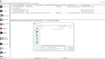
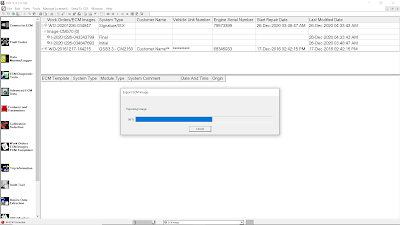
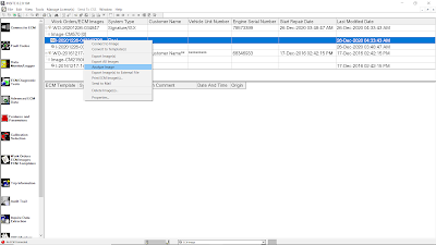
To open the Advanced ECM Data:
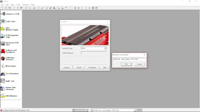
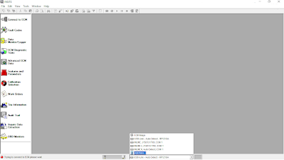
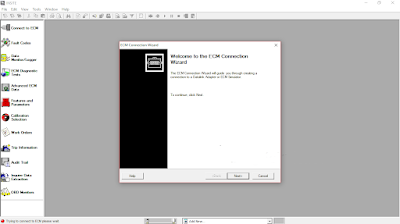
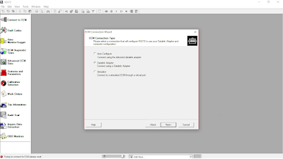
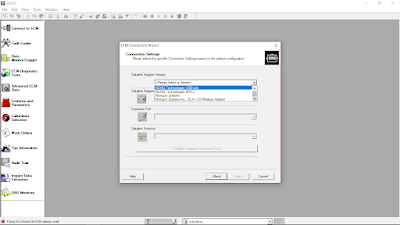
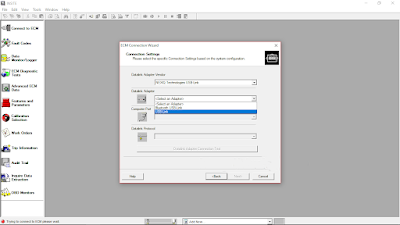
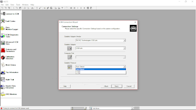
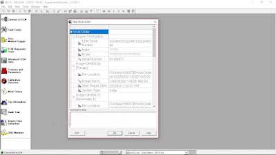
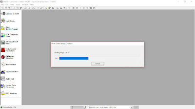
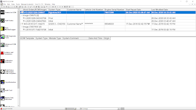
1). Connect diagnostic adapter tool (Nexiq USB-Link) to diagnostic port on Cummins Engine or ECM Image. Read More: How to Connecting CUMMINS Engines using Cummins INSITE Software.
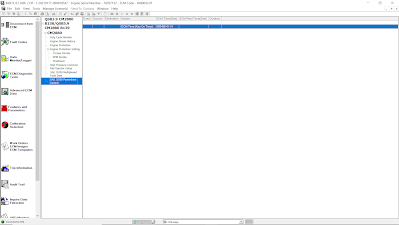
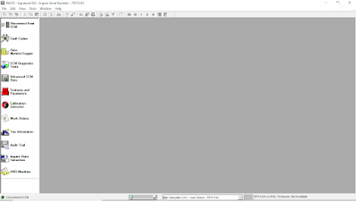
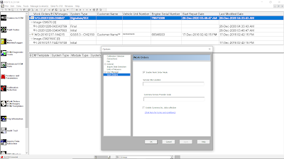
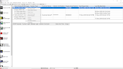
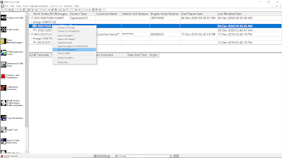
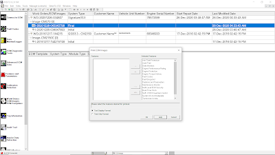
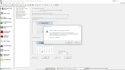
2). Click Advanced ECM Data on the Viewbar, as Figure 1.2 below.
Advanced-ECM-Data-on-Cummins-INSITE-Software-2

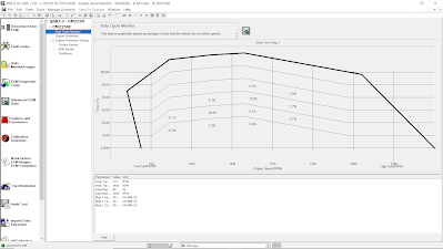
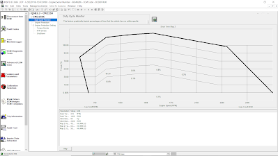
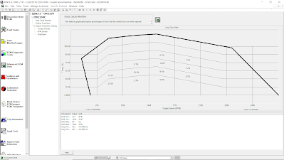
(A). Duty Cycle Monitor
The “Duty Cycle Monitor” graphically displays percentages of time that the vehicle has run within specific operating ranges. Operating ranges are based on engine speed (rpm) vs torque. Engine speed displays on the X axis and torque displays on the Y axis of the graph. The values for rpm and torque are defined by the calibration. A bold line is displayed on the graph as a generic torque curve reference. This curve is the same across all engines.

Each block on the graph shows an intersection of rpm values and torque values that represent a specific operating range for the vehicle. The number displayed in each block is a percentage of the total time that the vehicle operated in that range. For example, if a graph has a total of 500 hours of operating time with 5% displayed in a block, then the vehicle spent 25 hours operating within that range.

The total of the percentages displayed in the graph may be a little more or less than 100%. This is due to rounding when INSITE™ reads the data from the ECM.

Three different Duty Cycle maps can be displayed in the Duty Cycle Monitor window:
a). Short Term Map 1 (as Figure 1.1 above).
This map logs a total of 500 hours. When 500 hours has elapsed, INSITE automatically begins logging on Short Term Map 2.
b). Short Term Map 2.
This map logs a total of 500 hours. INSITE automatically begins logging on Short Term Map 2 after 500 hours have been logged on Short Term Map 1.
Advanced-ECM-Data-on-Cummins-INSITE-Software-3
c). Long Term Map.
This map records operating ranges over the file of the engine or vehicle. It can not be reset.
Advanced-ECM-Data-on-Cummins-INSITE-Software-4
Note: The parameter values will vary depending on which map is displayed.
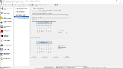
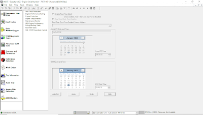
→Time Remaining – the amount of time remaining for the displayed map. The Short Term Maps last for 500 hours, and the Long Term Map is practically infinite.
→Map Start Time – the ECM time when logging began for the currently selected map.
→Advertised Power RPM – the engine speed at which the power peak is achieved.
→Advertised Power at RPM – the maximum horsepower rating for this engine.
→Replace Torque RPM – the engine speed at which peak torque is achieved.
→Peak Torque at RPM – the maximum engine power supported by this engine.

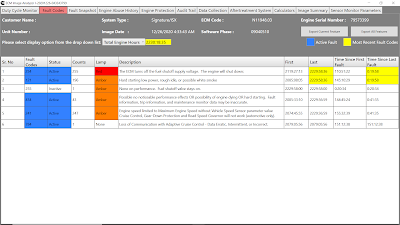
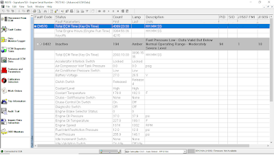
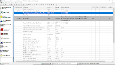
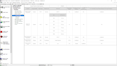
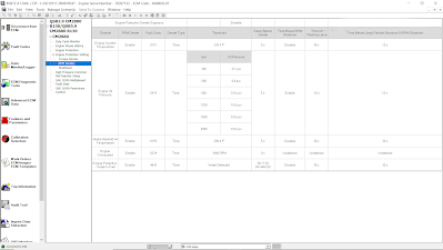
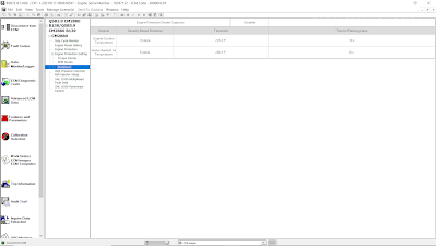
(B). Engine Protection Setting
Engine Protection is designed to prevent engine damage when a sensor value exceeds a certain limit for critical engine operating parameters. The Engine Protection feature enables you to view the Engine Protection fault history associated with a specific Engine Protection fault.

A fault history log is provided for each Engine Protection parameter. The last five occurrences of each Engine Protection fault are displayed.

Torque Derate/ RPM Derate
Advanced-ECM-Data-on-Cummins-INSITE-Software-5
Advanced-ECM-Data-on-Cummins-INSITE-Software-6

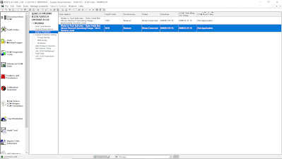
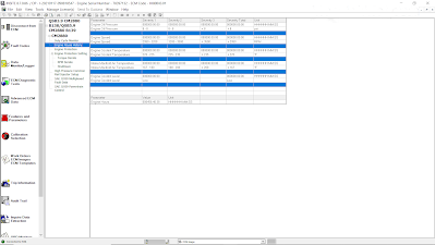
(C). Engine Protection
Advanced-ECM-Data-on-Cummins-INSITE-Software-7
Advanced-ECM-Data-on-Cummins-INSITE-Software-8

(D). Engine Abuse History
The Engine Abuse History feature tracks the time the engine has been running above recommended values for various engine parameters. This provides comprehensive data about the life of the engine, how it has been used, how it has been maintained, and what abuse it may have been subjected to.
Advanced-ECM-Data-on-Cummins-INSITE-Software-9

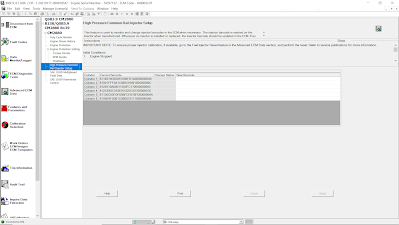
(E). High Pressure Common Rail Injector Setup
This special feature is used to display and update the barcode values for each injector installed on the engine. The Injector Barcode is an alpha-numeric character sequence, physically marked on the injector. This barcode indicates the injector’s fueling characterization. The ECM uses this information to adjust the injection commands, improving fueling accuracy and minimizing injector-to-injector fueling variations. It is important to update this information when an injector or ECM is replaced. The manual procedure should be used when replacing an injector. The import procedure should be used when replacing or ROM booting an ECM.
Advanced-ECM-Data-on-Cummins-INSITE-Software-10

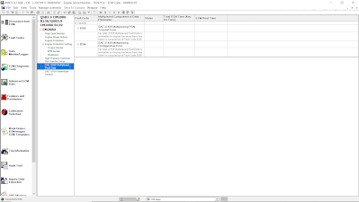
(F). SAE J1939 Multiplexed Fault Data
Advanced-ECM-Data-on-Cummins-INSITE-Software-11

(G). SAE J1939 Powertrain Control
SAE J1939 Powertrain Control enables on-board vehicle control devices such as Acceleration Slip Regulation (ASR) for traction control or electronically controlled transmissions to take control of the engine and/or engine subassemblies via the SAE J1939 datalink (network).

Use the SAE J1939 Powertrain Control feature to view a history of when the engine was controlled by a J1939 device. A record of attempts made to control the ECM through a J1939 device can be helpful during troubleshooting.
Advanced-ECM-Data-on-Cummins-INSITE-Software-12


2022年1月25日星期二

How to Connecting CUMMINS Engines using Cummins INSITE Software

How to Connecting CUMMINS Engines using Cummins INSITE Software

Cummins INSITE

How-to-Connecting-CUMMINS-Engines-using-Cummins-INSITE-Software-1

#To Connect to an ECM
1). Open Cummins INSITE through shortcut on desktop, using Status bar to select a connection options.

How-to-Connecting-CUMMINS-Engines-using-Cummins-INSITE-Software-2

2). Click the dropdown box on the Status bar to view a list of all currently available connection options, or click Add New to create one, then click Next.

How-to-Connecting-CUMMINS-Engines-using-Cummins-INSITE-Software-3

3). Use the ECM Connection Type page, and choose Datalink Adapter (Connect using a Datalink Adapter), then click Next.

How-to-Connecting-CUMMINS-Engines-using-Cummins-INSITE-Software-4

4). Select Connection Settings, Datalink Adapter Vendor, Datalink Adapter, and Datalink Protocol, then click Next.

How-to-Connecting-CUMMINS-Engines-using-Cummins-INSITE-Software-5
How-to-Connecting-CUMMINS-Engines-using-Cummins-INSITE-Software-6
How-to-Connecting-CUMMINS-Engines-using-Cummins-INSITE-Software-7

6). Click Connect to ECM.
→If you are connecting to a new ECM or an ECM without existing ECM passwords, select “None” in the Security Type: dropdown list.
→If you then want to define ECM security type passwords, select ECM Passwords on the Tools menu once connected to the ECM.

7). The Work Order Wizard is automatically displayed for you to create a work order for the selected connection, then click OK.
→You can disable the Wizard from starting automatically by unchecking the Enable Work Order Mode checkbox in the Work Orders page of the Options window. Read More: Work Orders on Cummins INSITE Software (CUMMINS Engines).

How-to-Connecting-CUMMINS-Engines-using-Cummins-INSITE-Software-8

8). Wait the Work Order/Image Creation until 100% of creating image.

How-to-Connecting-CUMMINS-Engines-using-Cummins-INSITE-Software-9
How-to-Connecting-CUMMINS-Engines-using-Cummins-INSITE-Software-10

2022年1月23日星期日

WORK ORDERS ON CUMMINS INSITE SOFTWARE (CUMMINS ENGINES)

Work Orders on Cummins INSITE Software (CUMMINS Engines)

Work Orders

Work-Orders-on-Cummins-INSITE-Software-1

#Work Orders – About
Work Orders are used to record and view information about the ECM history enabling technicians to reference previous ECM settings. Work Orders contain one or more images that contain a snapshot of all INSITE™ accessible data.

The Work Orders window is used to manage Work Orders, Images and Templates. The Work Order window has an upper and lower section. The upper section shows Work Orders and summary information. The lower section shows Templates.

Select Work Orders from the Viewbar (refer to Figure 1.1 above) to open the Work Orders window. When connected to an ECM or Simulator, INSITE™ will only display the work orders and images associated with that specific Engine Serial Number and it will only show Templates for that ECM type. If not connected, all Work Orders and Templates will be displayed.

Work Orders are initially sorted by the Last Modified Date, with the most recent Work Orders at the top. The list may be resorted by the values in any of the columns. To resort either list, click on the column header. The table will be resorted based on the selected column in ascending order. Click on the column header again to resort the table again in descending order. Columns may be moved by selecting the column header and dragging it to the desired location.

INSITE™ can be configured to automatically start the Work Order creation process when connecting to an ECM or Simulator by enabling the Work Order Mode. Work Order Mode will also start the image creation process before disconnecting from an ECM or Simulator. The Work Order creation will be started automatically but it can be cancelled if Work Order is not desired. Perform the following steps to enable or disable Work Order Mode:

Work-Orders-on-Cummins-INSITE-Software-2

a). Select Tools > Options from the Menu Bar.
b). When the Options window appears, select Work Orders from the left side of the screen.
c). When the Work Order screen is displayed, select or deselect the Enable Work Order Mode check box as desired.
d). Enter a Service Site Location.
e). Select OK to close the window.

#Work Orders – Parameters
The upper section of the Work Orders window contains a table that displays summary information that was recorded when the Work Orders and Images were created. The table has seven columns, explained below, and one row for each Work Order (refer to Figure 1.1 above).

1.Work Orders/ECM Images – This column displays the Work Order Name. When creating a Work Order, a default name is provided, but it can be changed if desired. The default name is “WO-” followed by the year, month, day, hour, minute, and second the work order was created. (Example: WO-20201226-034847 was created on December 26th, 2020 at 03:48:47 am).
2.System Type – This column displays the system type obtained from the ECM.
3.Customer Name – This column displays the Customer Name retrieved from the System ID and Dataplate.
4.Vehicle Unit Number – This column displays the Vehicle Unit Number retrieved from the System ID and Dataplate.
5.Engine Serial Number – This column displays the Engine Serial Number retrieved from the System ID and Dataplate.
6.Start Repair Date – This column displays the date and time that the first image was created in the work order.
7.Last Modified Date – This column displays the date and time that the most recent image was created in the work order.
#Work Orders – Right Click Menu

Work-Orders-on-Cummins-INSITE-Software-3

1.New Work Order – Select this option to open the Work Order wizard and create a new work order.
2.Delete Work Order(s) – Select this option to delete all data records associated with the selected work order(s).
3.Make Active – Select this option to activate a work order other than the current work order. When new Images are created, they are attached to the active Work Order.
4.New ECM Image – Select this option to create an ECM image of the selected work order.
5.Import Image(s) – Select this option to import a saved image file into the Work Orders window. Read More: ECM Images on Cummins INSITE Software (CUMMINS Engines).
6.Expand – Select this option to expand the selected work order to view its associated ECM images. Work Orders may also be expanded by selecting the icon to the left of the Work Order name.
7.Collapse – Select this option to collapse the selected work order, hiding its associated ECM images. Work Orders may also be collapsed by selecting the icon to the left of the Work Order name.
8.Print Work Order(s) – Select this option to print one or more work orders.
9.Properties – Select this option to view details about the Work Order. These details were created or edited when the Work Order was created or modified. Unlocked fields may be edited by double-clicking in the edit box and typing new data. Information may be added to the Technician’s Notes by clicking inside the box.

#Print ECM Image(s)
Select this option to print selected images. Multiple images can be printed by holding the Ctrl key while selecting the images to be printed. When printing multiple images, the print procedure will be performed for each image.

Work-Orders-on-Cummins-INSITE-Software-4

a). A Print ECM Images window will appear. All Features will be selected for printing and will appear in the right-hand window.

Work-Orders-on-Cummins-INSITE-Software-5

b). Add or Remove individual features to or from the Selected Features list by selecting the feature and then selecting the “-<” and “>-” buttons.
c). Add or Remove all features to or from the Selected Features list by selecting the “<<-” and “>>-” buttons.
d). Choose Tool Display Format or Text Only Format by selecting the appropriate radio button. Tool Display Format prints the data as displayed in INSITE™. Text Only Format prints the data in table format.
e). Select OK, and then proceed through the print wizard steps. Download here for example (Tool Display Format): ECM Images CM570 Final.pdf

Work-Orders-on-Cummins-INSITE-Software-6
Work-Orders-on-Cummins-INSITE-Software-7
Work-Orders-on-Cummins-INSITE-Software-8

#Export Image(s) to External File
Select this option to export selected Images to a Comma Separated Values file (.csv) or Text (.txt). An Export Location window will appear. Select the desired file location and edit the file name, if desired. The default name “I-” is followed by the year, month, day, hour, minute, and second the work order was created. The file may be viewed using third party software applications including “Microsoft Excel”. Comma Separated Values and Text files cannot be imported back into INSITE™.

Work-Orders-on-Cummins-INSITE-Software-9
Work-Orders-on-Cummins-INSITE-Software-10
Work-Orders-on-Cummins-INSITE-Software-11

#Analyze Image
Select this option to using Image Analyzer for each Parameters, and Export the Features.

Work-Orders-on-Cummins-INSITE-Software-12
Work-Orders-on-Cummins-INSITE-Software-13

2022年1月20日星期四

ECM Time on Cummins INSITE Software (CUMMINS Engines)

ECM Time on Cummins INSITE Software (CUMMINS Engines)

ECM Time – Engine Hours

ECM-Time-on-Cummins-INSITE-Software-1

During operation of the Engine, the ECM records and stores information related to a wide range of events, which includes time stamping. Two different measures of time are available:
1). ECM Time (Key On Time), which is the cumulative ECM hours (HH-MM-SS), refer to Figure 1.1 above, while Engine Hours (Engine Run Time) is cumulative time as the Engine is running (HH-MM-SS).

ECM-Time-on-Cummins-INSITE-Software-2

2). ECM Real Time, which gives a date and 24 hours based time stamp. This feature allows automatic synchronization of ECM Real Time to match the PC Date and Time or a manual change to enter the current ECM Real Time. It is also important to ensure that the local time zone is set correctly to maintain the correct local time.

A battery backup is used to maintain constant power to the Real Time Clock. If the battery backup is not present, a power loss to the Real Time Clock (such as disconnecting the batteries in excess of 5 seconds) causes a loss of Real Time Clock accuracy. This situation generates fault code 319, and the maintenance lamp will light.

#Enabling the Real Time Clock
To enable the Real Time Clock:
a). From Advanced ECM Data, select Real Time Clock. Read More: Advanced ECM Data on Cummins INSITE Software (CUMMINS Engines).

ECM-Time-on-Cummins-INSITE-Software-3

b). Select the Enable Real Time Clock checkbox.

ECM-Time-on-Cummins-INSITE-Software-4

c). The Real Time Clock can either be set automatically or manually:
→Automatically setting the Real Time Clock
-Verify that the Local PC Date and Time are correctly displayed. If this needs to be corrected, it must be done within Windows. Select Undo and close INSITE™. Adjust the PC Date and Time as needed. If the Local PC Time and Date are correct, select the Auto Set button.
→Manually setting the Real Time Clock
-Verify that the Local Time Zone is correct, and then set the correct date and time in the ECM Date and Time frame. Select Apply to save these settings to the ECM.
d). Follow the prompts to save the changes to the ECM.

ECM-Time-on-Cummins-INSITE-Software-5

Note: Once enabled, the Real Time Clock can NOT be disabled and ECM cumulative hours are no longer available.
e). Select Undo to exit the Real Time Clock window without sending changes to the ECM.