2021年8月20日星期五

How to Reset/Upload ECM Data for ISUZU 2020 4JJ3 Truck

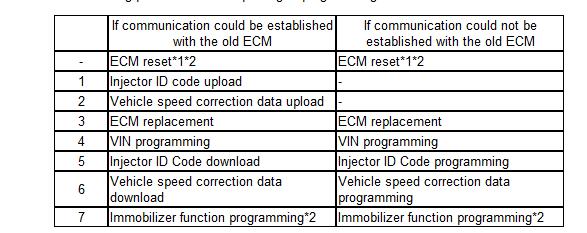
 When replacing the ECM, the vehicle data must be written into the new ECM. The scan tool used for the replacement procedure must be the same from start to finish. If the scan tool is changed midway, information cannot be written correctly. So this instruction show you guide on how to reset/upload ECM data for ISUZU 2020 4JJ3 AWR6B45 truck.

How-to-Reset-Upload-ECM-Data-for-ISUZU-2020-4JJ3-Truck-1

Use the following procedure when replacing or programming the ECM.

How-to-Reset-Upload-ECM-Data-for-ISUZU-2020-4JJ3-Truck-2

Preparations:

Isuzu G-IDSS Export Diagnostic Software Free Download

ISUZU N-Series Fuel Injector Flow Rate Programming by IDSS

Note:

*1: If reusing the ECM in another vehicle, perform the ECM reset in the original vehicle.

*2: Perform only for models with immobilizer.

Caution:

Because “ECM reset” cannot be performed in a new vehicle, be sure to perform “ECM reset” in the original vehicle.

1.ECM Reset

Caution:

When installing the ECM to the vehicle, it must be security linked to the wireless access module using the programming procedure. Once this linking has been performed, the ECM cannot be installed to any other vehicle. Before transferring (switching) to the vehicle in which the complaint originated, the resetting procedure must be performed in the original vehicle and the security linkages between each module must be reset.

If the ECM to be replaced cannot establish communication with the scan tool, do not perform this operation.

1) Connect the scan tool to the DLC.

2) Turn ON the ignition switch.

3) Select the scan tool item.

Diagnostics > Body > WAM (Wireless Access Module) > Special Function > Engine Control Module > Reset Engine Control Module

4) Erase the immobilizer information of the ECM by following the on-screen instructions.

Caution:

Entering an incorrect security code causes a security wait time.

Note:

When turning the ignition switch ON and OFF by following the on-screen instructions, wait at least 5 seconds before turning it OFF or ON each time.

5) Turn OFF the ignition switch for 30 seconds.

6) Verify that the engine does not start with all the keys.

2.ECM data upload

1) Upload the following data from the old ECM to the scan tool.

Injector ID Code

Vehicle speed correction data

3.Injector ID code upload

1) Connect the OBD2 scan tool to the DLC.

2) Turn ON the ignition switch.

3) Select the scan tool item.

Diagnostics > Engine > 4JJ3 > Programming > Injector ID Code > Upload Injector ID

4) Follow the directions on the screen and upload the injector ID codes to a scan tool.

4.Vehicle speed correction data upload

1) Turn ON the ignition switch.

2) Select the scan tool item.

Diagnostics > Engine > 4JJ3 > Programming > Vehicle Speed Correction Data > Upload Vehicle Speed Correction Data

3) Upload the vehicle speed correction data to the scan tool by following the on-screen instructions.

4) After completing the upload, turn off the scan tool.

5) Turn OFF the ignition switch.

2021年8月18日星期三

JCB Electronic Service tool with JCB Service Master 4 V1.73.3 Heavy Duty Truck Diagnostic Scanner


JCB Electronic Service tool with JCB Service Master 4 V1.73.3 Heavy Duty Truck diagnostic Scanner

JCB-Electronic-Service-tool-1

1. Lastest Software Version: V1.73.3 (We also have V8.1.0 and v1.45.3 software , if you need it , we can offer to you )
2. Language: English, French, German, Italian, Portuguese, Spanish
3. Update By Email

Description:
JCB Electronic Service Tool diagnostic interface is used for fast and effective fault finding, check maintenance standards, see if the machine has been abused, view and change machine set up data, flash ECUs with the correct data files. You can reset EMS hours, edit speed limiters and use other functions what require special unlock.

JCB Service Master is a gateway application allowing a large number of Vehicle Support Applications to be linked using one familiar interface. The interface acts as a graphical tool for selecting the target vehicle from a groups of Vehicle Families and triggering the particular Service Tool Application desired. This removes the need for a user to ‘remember’ every individual service tool available and select which one if intended for a particular machine.

The JCB Service Master also provides several key features that will accompany all JCB projects, a Multi Language editing tool that provides a means of individual text string translation for all JCB Applications and a means to select a localised language translation for the each JCB Application.

JCB Electronic Service Tool Feature:
1. Reads fault codes and ranks them in order of importance.
2. Calibrates, parameterize ECM and program blocks.
3. Conducts dropping service intervals.
4. Compatible with software JCB Service Master 4 (2019).
5. It works with CAN protocol in OBD II system.
6. It is provided with instructions for use, repair and diagnostics of vehicles JCB engines and Isuzu, Deutz, Cummins.
7.  Full original JCB repair and service manuals and bulletins
8.  JCB spare parts for all markets
9.  Programming special parameters (order separately)
10. Supported languages: English, German, Spanish, French, Italian, Portuguese.

JCB Service Tool Supported Models and Engines
Agricultural models:
1. Fastrac Tractors (2000-3000, 3000 Series
2, 3000 Series 3, 3000 Series 4, 7000 Series, 8250 Series 1, 8250 Series 2, 8000 Series 3), 2. Telescopic Handlers (2007-, 2007+, Tier 4, 525-60 Compact Loadall),
3. Wheeled Loading Shovels (Large, Large 2012+, Compact (Tier 4 CWLS), Medium (411, 413 ,417, 418S Tier 4i)
4. Telemasters (TM180/220, TM310, TM320)

Construction models:
1. Backhoe Loaders,
2. AMS/DECU Machines (Tracked (JS/JZ/JZ70), Wheeled),
3. Compact Excavators (Mini/Midi) (801-8065, 8080-8085,65R1-86C1),
4. Telescopic Handlers (2007-, 2007+, Tier 4, 525-60 Compact Loadall),
5. Skidsteer Loaders (Robot, Other), Teletrucks (Tier 4),
6. Wheeled Loading Shovels (Large, Large 2012+, Compact (Tier 4 CWLS), Medium (411, 413 ,417, 418S Tier 4i)),
7. Telemasters (TM180/220, TM310, TM320)),
8. Articulated Dump Trucks, Vibratory Compactors (Tier 3, Interim Tier 4, VMT380/430),
9. Rough Terrain Forklifts (Tier 2/3 RTFL, Tier 4 RTFL), 10. Teletruks (Tier 4).

Waste models:
Telescopic Handlers (Tier 3, Tier 4).

Engines:
1. Dieselmax and Dieselmax 672 (IPU, OEM Base, G Drive), 2. Ecomax (IPU, OEM Base, G Drive), Kohler TCR Engine. 3. Generators: G46X/QX, G141X/QX, G165S/QS, G200S/QS, G220S/QS.

Package including:
1.Data Link Adapter
2.USB cable
3.9-pin Deutsch adapter
4.6-pin cable
5.JCB Service Master Diagnostic Software CD

JCB-Electronic-Service-tool-2
JCB-Electronic-Service-tool-3
JCB-Electronic-Service-tool-4
JCB-Electronic-Service-tool-5

2021年8月16日星期一

JCB Electronic Service Tool With Free SM4 V1.73.3 Software

 JCB Electronic Service Tool Heavy truck scanner comes with JCB Service Master 4 V1.73.3 software in CD, supports multi language. JCB Service Master is a gateway application allowing a large number of Vehicle Support Applications to be linked using one familiar interface.

JCB Electronic Service Tool Description
1. JCB Service Master is a gateway application allowing a large number of Vehicle Support Applications to be linked using one familiar interface.
2. The interface acts as a graphical tool for selecting the target vehicle from a groups of Vehicle Families and triggering the particular Service Tool Application desired. This removes the need for a user to ‘remember’ every individual service tool available and select which one if intended for a particular machine.
3. The JCB Service Master also provides several key features that will accompany all JCB projects, a multi language editing tool that provides a means of individual text string translation for all JCB applications and a means to select a localized language translation for the each JCB application.

JCB Electronic Service Tool Highlights:
1. Reads fault codes and ranks them in order of importance.
2. Calibrates, parameterize ECM and program blocks.
3. Conducts dropping service intervals.
4. Compatible with software JCB Service Master 4 (2019).
5. It works with CAN protocol in OBD II system.
6. It is provided with instructions for use, repair and diagnostics of vehicles JCB engines and Isuzu, Deutz, Cummins.
7. Full original JCB repair and service manuals and bulletins
8. JCB spare parts for all markets
9. Programming special parameters (order separately)
10. Supported languages: English, German, Spanish, French, Italian, Portuguese.
JCB Electronic Service Tool Supported Models and Engines:

JS Range, JZ70, BackHoe Loader, Loadall 2007-, Loadall 2007+, Robot, Teletruk, Midi Excavator, Dump Truck, Fastrac 2000-3000 Series, Fastrac 8250 Series 1, Fastrac 8250 Series 2, Fastrac 7000 Series 1, Large Wheel Loading Shovels, Vibromax, JCB Dieselmax Engine, JCB Engine (IPU OEM), JCB Engine (Base Engine OEM), JCB Generators, LiveLink.

JCB Electronic Service Tool Software Display


Packing List
1 x JCB Electronic Service Tool Diagnostic Interface
1 x 9 Pin and 6Pin Cable
1 x USB Cable
1 x JCB Service Master Diagnostic Software CD

END.

2021年8月14日星期六

How to install and active CNH EST 9.4 software

 How-to-install-and-active-CNH-EST-9.4-software

New Holland Electronic Service Tools CNH EST 9.4 Up. 6 Diagnostic Software

Holland electronic service tools (CNH EST 9.4 Engineering software) + does not expire + diagnostic procedures

New Holland Electronic Service Tool-Complete Diagnostic for New Holland Kobelco Case Steyr Flexicoil and / O&K New Holland Construction and New Holland Farm Equipment. Construction of housings and equipment for agriculture.

How to install and active CNH EST 9.4 software Video:

https://www.youtube.com/watch?v=_gT5zLy5zaM

Supported languages: English, Italian, Russian, Polish, Spanish, French, Portuguese, German, Dutch, Danish.

Region: All regions
Languages: English, Spanish, Italian, Mexican, German, Norwegian, Russian, FRENCH
OS: VISTA Win7.8.10 … Win98 … WinJapan … WinNT … WinXP
CD Quantity: 2 DVD
Update date:

The product only for a pc installation

Electronic Service Tool 9.0 (EST) Engineering Level * (software only) – used by New Holland dealer technicians to connect with vehicles that have a Controller Area Network (CAN) BUS.

The new version of new Holland CNH EST software works with OS Windows 7 32/64 bit / 8 32/64 bit / 8.1 bit / 10 32/64 bit / 10 32/64 bit, except Home Edition).
* For advanced dataset logging and a host of hidden vehicle scheduling options, raw message simulations

Important announcement! Service Manuals, schematics available online only. The item does not include it

The latest version of CNH EST software with technical documents is 7.6.

The electronic service tool allows you to:
• Check the status of the parameters;
• Recover defects;
• Run diagnostic tests;
• Do the ECU and parameter programming;
• Monitors active and logged diagnostics;
• View and change the ECU configuration;
• View diagnostic procedures and schematics.
• Problem solving problems;
• Use the assist database;
• Run scoping diagnostics;

We recommend using our free remote assistance with the setup and activation process.

If you have advanced computer skills, we can provide you with all the information for installation and activation

CNH EST software can be loaded down, or we can ship it as a DVD set
https://www.obd2tool.com/goods-10452-New-Holland-Electronic-Service-Tools-CNH-EST-Diagnostic-Software.html

New Holland Electronic Service Tools (CNH EST 9.4 9.2 8.6)CNH DPA5 kit diagnostic tool Plus lenovo T420 laptop

According to the software version you choose, we will install the corresponding version of the software in the lenovo T420 laptop. You can use it directly after receiving the goods.

2021年8月12日星期四

Perkins SPI2 2018A EPC+Service Manual Free Download

 What is Perkins SPI2 2018A?

Perkins SPI2 2018A is Service & Parts Information (SPI) for Perkins machine,it enables you to quickly and simply call up spare parts and service information. The system software is found on your SPI DVD and is available for use under license from Perkins Engines Ltd. All aftermarket parts and service information is available at a glance – from the illustration and part number to the repair and maintenance instructions.

Perkins SPI2 2018A Features:
Size:4.7GB rar file
Date:2018
Region: All regions
Languages: English, German, French
Win: Windows XP,Windows 7,Windows 10

Perkins SPI2 2018A Functions:
Service Manuals
Service Bulletins
Service Letters
Parts Marketing Bulletins
Product Bulletins
Parts Comparison Bulletins
Parts Kit Instructions
Service Tooling
Electrical Connectors
Parts Pictures
Special Instruction
Chinese Service Manual
Translated Service Manual

Perkins SPI2 2018A Support Models:
100 Series
200 / 300 Series
400 Series
500 Series
700 / 800 Series
850 Series
900 / 3.152 Series
900 Series
1000 (4 Cyl) / 4.236 Series
1000 (6 Cyl) / 6.354 Series
1050 Series
1100 Series
1200 Series
1300 / Peregrine Series
1500 Series
1600 Series
2000 / 3000 Series
2200 / 2300 / 2500 / 2800 Series
4000 Series
V8 540 / 640
Miscellaneius
SOS Catalogues

2021年8月10日星期二

How to Remote Switches by Caterpillar ET Software

 How to Remote Switches by Caterpillar ET Software

How-to-Remote-Switches-by-Caterpillar-ET-Software-1

1). Use CAT ET to Check the Programming of the Parameter Dedicated PTO Parameters.
→Connect CAT ET to the data link connector. Read More: How to Connecting Caterpillar ET Software to the ECM.
→Access the Dedicated PTO Parameters on Cat ET. Note the programming of the parameter PTO Configuration (Remote Switches).

How-to-Remote-Switches-by-Caterpillar-ET-Software-2

2). Check the Circuit for the PTO On/Off Switch.
→Turn the Ignition Key Switch to the ON position.
→For the Input 1 (PTO On/Off switch), access the CAT ET Status screens that display the following status parameters. Read More: Status Tool on Caterpillar ET Software.

PTO Config (Remote Switches)
PTO On/Off Switch

→Verify that each of the interlocks for the PTO are set. Then, while the CAT ET Status screen is being monitored, move the PTO On/Off Switch to the ON position and move the PTO On/Off Switch to the OFF position.
How-to-Remote-Switches-by-Caterpillar-ET-Software-3

3). Check the Status of the Set/ Resume Input.
→View the Status parameter on CAT ET for the Remote PTO Set Switch and for the Remote PTO Resume Switch.
→While the Status screen of CAT ET for the switch is being monitored, perform the following procedure in order:
-Put the Remote PTO Set/Resume Switch in the Set position. The status of the Remote PTO Set Switch changes from “OFF” to set switch “ON” when the Remote PTO Set Switch is moved to the SET position, and the Engine RPM will increase.

How-to-Remote-Switches-by-Caterpillar-ET-Software-4

-Put the Remote PTO Set/Resume Switch in the Resume position. The Status of the Remote PTO Resume Switch changes from “OFF” to resume switch “ON” when the Remote PTO Resume Switch is moved to the RESUME position, and the Engine RPM will decrease.

How-to-Remote-Switches-by-Caterpillar-ET-Software-5

-Also monitor the Status of the PTO Set RPM, will changes from 0 RPM to actual Engine Speed (will equal) and the PTO Kickout (Not Kicked Out).

How-to-Remote-Switches-by-Caterpillar-ET-Software-6

-PTO Kickout value will changes to PTO Switch Turned Off when the PTO On/Off Switch is turned to the “OFF” position.

How-to-Remote-Switches-by-Caterpillar-ET-Software-7
4). Monitor using the Real Time Graphing while simulate the PTO Configuration test (Remote Switches).

How-to-Remote-Switches-by-Caterpillar-ET-Software-8

When the PTO Configuration is programmed to Remote Switches or to Remote Throttle and the PTO On/Off Switch is On, the following circuits are ignored:
• Service Brake Pedal Position Switch 1
• Service Brake Pedal Position Switch 2
• Clutch Pedal Position Switch
• Neutral Switch
• Accelerator Pedal Position Sensor
• Cruise Control Set/Resume Switch that is located in the Cab.

2021年8月8日星期日

How to Install and Resigter JPRO Professional software 2019 v2

 JPRO® Professional is the most comprehensive and powerful all makes, all models diagnostic tool available in the industry today. In one, easy annual subscription, JPRO provides a complete & unparalleled diagnostic service & repair solution with bi-directional functionality.

Next Step Service Information module helps speed up repair times by providing users with detailed engine repair information and troubleshooting guides for ABS and Transmissions – with the click of a button.

Noergon’s DLA+ 2.0 adapter is a diagnostic communication device designed to interface between a vehicle and PC via USB cable for diagnostic and vehicle information, re-programming or parameter adjustments.

Noregon JPRO Commercial Fleet Diagnostics 2019v2 Installation and Activation

https://www.youtube.com/watch?v=01skyq4jsSY

Part 1. How to Install JPRO Professional software 2019 v2

1.Close all other running applications.
2.Insert the JPRO® USB Flash Drive into a USB port on your computer.
3.Open Windows/File Explorer and click on the USB drive.
4.Double click the “Setup” file to launch the installation window.
Internet connectivity is required for registration.

5.Click the “Install JPRO“ button. Follow the on-screen installation instructions.
6.When the installation has completed, close the Installation screen.
7.Install the DLA drivers by clicking the “Install DLA Drivers”
button.
8.Follow the on-screen instructions and the separate DLA QuickStart Guide to complete the installation.

Part 2. How to Resigter JPRO Professional software 2019 v2

1.JPRO Commercial Vehicle Diagnostics requires registration before the application may be used. Double-click the application’s icon located on the desktop. You will be prompted to register the product.
2.Click the “Edit” Button in the Customer Information section to add your contact information. You will be required to provide an email. It must be a valid email that you can access.
3.Enter all license keys that you purchased in the License Key designated area and click the “Add” button.

4.Click the “Register” button. The information will be sent to Noregon’s licensing servers over the internet. The licensing servers will send you an email with a confirmation code. You must provide the confirmation code when prompted in order to complete the activation process.
Internet connectivity is required for registration.
5.Once registration is successful, you may begin using JPRO Professional.
6.Click “Help” then select “View User’s Guide” from the JPRO® Professional main toolbar for detailed information about application features. You can also access the User’s Guide by clicking “Connect” from the main menu then clicking the “How To” button from the Connect Window.

2021年8月6日星期五

How to Solve No Communication between the Vehicle and SDP3

 This post show you guide on how to solve “No communication between the vehicle and SDP3”.

Related Contents:

Newest Scania SDP3 Diagnostic Software Free Download

To be able to troubleshoot in the CAN network it is important to be aware of some basic factors. The CAN technology has been developed to provide a reliable transfer of data between different components in the vehicle. It is based on serial communication in 2 cables, called CAN-high (CAN H) and CAN-low (CAN L). In certain cases there is also a shield cable which counteracts interference.

To reduce the risk of the CAN bus becoming overloaded with messages, Scania has chosen to mainly divide the ECU systems into 4 CAN buses. These are called yellow, green, red and orange CAN bus.In addition to these, there is also a network for external CAN communication designated with the colour blue.

Besides these CAN buses, there may be additional CAN buses, designated with the colour grey. For example, some of the units in the CCS system communicate by using an internal CAN network. The ECU systems that are most important for driving the vehicle (BMS, COO, EMS and GMS) are connected together on a CAN bus (red bus). Scania Diagnos (Scania Diagnosis & Programmer 3) is connected to the green bus.

Junction blocks distribute the CAN bus signals to the control units on the same CAN bus. They are available in different versions depending on whether they connect networks in the cab or on the
chassis.

Fault code descriptions
If SDP3 cannot identify any control units, you will not get any fault code descriptions in the program. You can solve this by going to the SDP3 menu under View > Search fault codes. There, you can get a list of fault code descriptions per assembly part number. You can the obtain assembly part numbers via the diagnostic mode (IVD) in the instrument cluster (ICL), provided that the instrument cluster can establish contact with the control units and that there are fault codes.

It is not the fault codes that are the most important in this case, since it is the communication you want to test. If the instrument cluster responds no errors it means that the communication is working.

Termination resistors on the CAN bus
As the voltage between CAN-high and CAN-low varies the whole time, depending on whether a 1 or a 0 is sent, you cannot control the CAN communication using a multimeter. You can, however,
check that the CAN bus termination resistors are intact by measuring the resistance between CAN-high and CAN-low using a multimeter.

The illustration on the next page shows the junction blocks that are connected to the coordinator and the size of each termination resistor.
The measuring should be performed on the coordinator’s pin for each CAN bus with the connector connected. For example, the measuring of the green CAN bus can be performed at the coordinator’s E30.B connector between the measuring points B-3 and B-12.

Note:
To be able to measure the resistance in a CAN bus, all systems must be connected and with no power to the vehicle when measuring.

The resistance for each CAN bus must be 54-60 ohm. If the resistance is 120 ohm, this means that 1 termination resistor is missing. If the resistance is 40 or 30 ohm, then there is/are 1 or 2 termination resistors too many on the particular CAN bus. In case of too high or low resistance in the CAN bus,the next step is to measure the termination resistors for the coordinator, junction blocks and connected control units separately.

The coordinator’s and connected control units’ termination resistors are measured at the control units’ pin for each CAN bus without connectors being connected. The measured value for the coordinator should be 120 ohm. The measured values for the connected control units should be as shown in the illustration above.

The junction blocks’ termination resistors are measured on each separate junction block without connector. Check measuring of a junction block’s termination resistor is performed by measuring the upper and lower rows of pins. The middle row is used for shielding. The resistance for a separate junction block should be 120 ohm or 2.6 kohm depending on the version.

Voltage in CAN bus
It is not possible to measure the voltage in the CAN bus to see if it varies in the circuit. The multimeter only measures the average of the CAN bus’s voltage levels, but this can give sufficient information to assess the CAN bus’s electrical condition. The voltage between CAN-high and CAN-low varies the whole time depending on whether it is a 1 or 0 that is sent. When a 1 is sent, CAN-high and CAN-low are 2.5 V. When a 0 is sent, CAN H rises to approx. 4 V and CAN L drops to approx.1 V. This happens so quickly that you cannot see it on a regular multimeter. The average value shown on the multimeter should therefore be approx. 2.5 V when you measure between CAN-high and ground and CAN-low and ground. In case of too high or too low voltage in the CAN bus, the next step is to check if the CAN bus is short-circuited to the voltage supply or ground. To check if this is the case, the following measurements must be performed for the specific CAN bus. The resistance must be in the order of a megaohm and the measuring must be performed without power in the vehicle.
• Measure the resistance between CAN-high and voltage supply.
• Measure the resistance between CAN-high and ground.
• Measure the resistance between CAN-low and voltage supply.
• Measure the resistance between CAN-low and ground.

Overload in CAN bus
Faults may occur in ECU systems which make them send erroneous messages all the time in such a quantity that the communication does not work. This is called overload. Overload can cause certain messages to be forwarded and others not. Which in turn means that certain functions will fail.

If the green CAN bus is overloaded, this can also mean that SDP3 cannot be used. In case of overload on a CAN bus, one control unit at a time should be disconnected to see if the problem disappears and thereby identify the defective control unit.

Troubleshooting: No communication between the vehicle and SDP3
1.Check VCI – indicator lamps show status. Try to start the program again.
2.Check ICL – which systems should be there? Compare with the CAN bus chart.
3.Can ICL communicate with systems on the green CAN bus?
a) If yes, the fault is towards VCI or there is a fault in the connection to the truck or in the junction block (C479).
4.Check that the resistance on the green CAN bus between CAN-high and CAN-low is 54-60 ohm.
All systems must be connected and the vehicle without power when measuring.
a) In case of fault, check the coordinator’s, the junction block’s and connected control units’ termination resistors separately.
5.Check the voltage level for CAN-high and CAN-low in relation to the chassis ground point on the green CAN bus. The value should be approx. 2.5 V.
a) In case of fault, check the resistance between CAN-high/CAN-low and ground/voltage supply respectively. The resistance must be in the order of a megaohm or more.
– In case of fault, perform the same type of measuring on the junction block to find out in which branch of the green CAN bus there is a fault.
– Disconnect the control unit in question so that you can distinguish between faults in the control unit and faults in the cable harness. In case of fault in the cable harness – troubleshoot the
electrical cables.
6.Check that there is no overload on the green CAN bus. Disconnect one control unit at a time to see if the problem disappears and thereby identify the defective control unit.
For more information, see the Workshop Manual > 16 – 00 > Electrical system complete > CAN network.

2021年8月4日星期三

NEW HOLLAND ELECTRONIC SERVICE TOOLS (CNH EST 9.4) UPD. 4 (REPLACES V9.3) DIAGNOSTIC SOFTWARE


Electronic Service Tool 9.4 (EST) Engineering Level* (software only) – used by New Holland dealer technicians to connect with vehicles that have a Controller Area Network (CAN) BUS.
The brand new version of New Holland CNH EST works with OS Windows 8 64 bit / 8.1 64 bit / 10 64 bit, except Home editions). If you have windows 7, we can offer you a previous version of CNH EST, as the 9.4(9.3) versions no longer support Windows 7 and in some cases won’t even loading.
*for advanced dataset registration and a lot of hidden options programming for vehicles, raw message simulations.

Optionally, you can purchase eTimGo for CNH EST 04.2021 for all brands OFFLINE which is a completely offline repair and diagnostics information database. With PIN search support.

The software EST v9.4 comes as:

CNH EST 9.4.0.0.0 installation file,
CNH EST 9.4.0.0.2 (EST9400Up1) update,
CNH EST 9.4.0.0.3 (EST9400Up2) update,
CNH EST 9.4.0.0.4 (EST9400Up3) update,
CNH EST 9.4.0.0.5 (EST9400Up4) update,
Vehicle Controller Files v46,
Legacy Multilanguage Diagnostic Procedures installer,
Optionally, by request, with Additional assistant Programs,
PC Locked Activation tool with the engineering access level.
The software EST v9.3 comes as:

CNH EST 9.3.0.0.0 installation file,
CNH EST 9.3.0.0.2 – 9.3.0.0.7 (EST9300Up5) updates,
Legacy Multilanguage Diagnostic Procedures installer,
Optionally, by request, with Additional assistant Programs,
PC Locked Activation tool with the engineering access level.

What’s new in the CNH EST v9.2 upd. 1 – 10

EST_9200_Update_1_Details

EST_9200_Update_2_Details

EST_9200_Update_3_Details

EST_9200_Update_4_Details

EST_9200_Update_5_Details

EST_9200_Update_6_Details

EST_9200_Update_7_Details

EST_9200_Update_8_Details

EST_9200_Update_10_Details

IMPORTANT NOTICE. Service Manuals, Schemes available only online.

In case if your PC/Laptop doesn’t fit with the minimum hardware requirements, we can offer the CNH EST v9.0 (2019/01), which is still compatible with the 32-bit windows and 3/4 Gb of RAM. Please indicate the desired application version in the comments field. Or via the contact us form.

New minimum PC specifications

All computers must use a 64-bit version of their operating system. The older 32bit options are limited to 4 gigabytes of RAM, and cannot provide enough performance to run these programs.

Minimum Specifications

Processor: Intel Core i5 Processor or higher;

RAM Memory: 8 GB or greater;

Operating System: Windows OS: 64-bit (Mandatory)

Windows 7

Windows 8.x

Windows 10 (Recommended)

Hard Drive: 250 GB or greater;

Ports: One 9 pin Serial port (preferred) OR USB to RS-232

Converter – FTDI Chipset)

Two USB ports

10/100 Ethernet

WiFi 802.11b / g

Bluetooth

Mobile Wireless (recommended)
The following brands of the CNH group are covered:

New Holland (Agriculture and Construction)
New Holland FK (Fiat-Kobelco)
New Holland O&K (Orenstein & Koppel)
CASE (Agriculture and Construction)
STEYR
KOBELCO
Iveco (Astra) (articulated dump trucks only)
Flexi-Coil
Sumitomo (S.H.I.)
Link-Belt

The last version of CNH EST with technical documents is 7.6. If you need electrical schemes, please consider purchasing CNH EST 7.6 version on virtual PC with Windows XP Works with any Windows platform.

New Holland Electronic Service Tool allows you to:

• Check the status of parameters;
• Retrieve faults;
• Run diagnostic tests;
• Make ECU and parameter programming;
• Monitor active and logged diagnostics;
• View and change ECU configuration;
• View diagnostic procedures and schematics.
• Troubleshoot problems;
• Run scope diagnostics;

CNH EST can be downloaded, or we can send it as a set of DVDs

We recommend using our free remote assistance with the setup and activation process.
If you have advanced Computer Skills, we can provide you with all the information for installation and activation

Screenshots for New Holland Electronic Service Tools (CNH EST 9.4) Upd. 4 (replaces v9.3) Diagnostic Software: