This post show you guide on how to solve “No communication between the vehicle and SDP3”.
Related Contents:
Newest Scania SDP3 Diagnostic Software Free Download
To be able to troubleshoot in the CAN network it is important to be aware of some basic factors. The CAN technology has been developed to provide a reliable transfer of data between different components in the vehicle. It is based on serial communication in 2 cables, called CAN-high (CAN H) and CAN-low (CAN L). In certain cases there is also a shield cable which counteracts interference.
To reduce the risk of the CAN bus becoming overloaded with messages, Scania has chosen to mainly divide the ECU systems into 4 CAN buses. These are called yellow, green, red and orange CAN bus.In addition to these, there is also a network for external CAN communication designated with the colour blue.
Besides these CAN buses, there may be additional CAN buses, designated with the colour grey. For example, some of the units in the CCS system communicate by using an internal CAN network. The ECU systems that are most important for driving the vehicle (BMS, COO, EMS and GMS) are connected together on a CAN bus (red bus). Scania Diagnos (Scania Diagnosis & Programmer 3) is connected to the green bus.
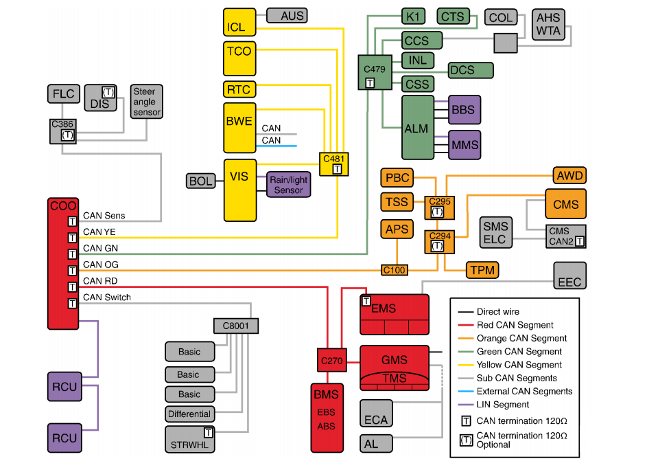
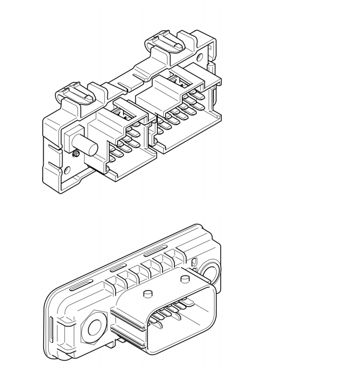
Junction blocks distribute the CAN bus signals to the control units on the same CAN bus. They are available in different versions depending on whether they connect networks in the cab or on the
chassis.
Fault code descriptions
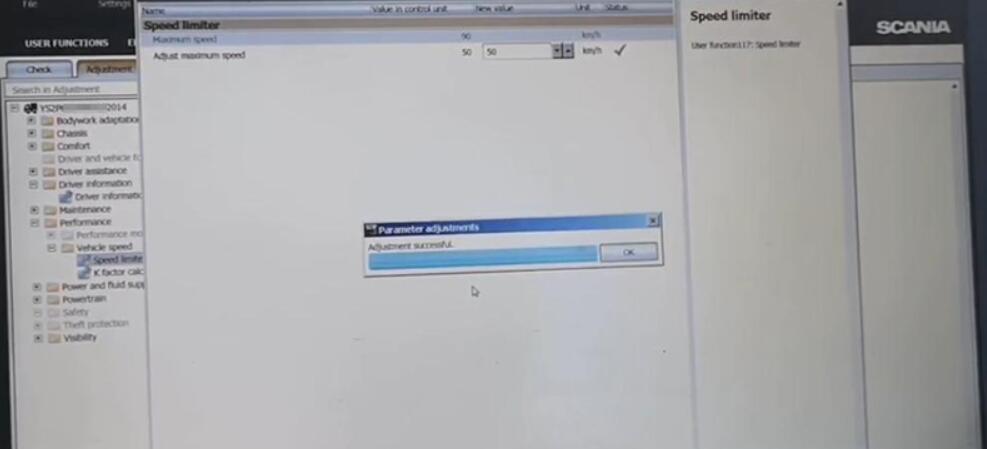
If SDP3 cannot identify any control units, you will not get any fault code descriptions in the program. You can solve this by going to the SDP3 menu under View > Search fault codes. There, you can get a list of fault code descriptions per assembly part number. You can the obtain assembly part numbers via the diagnostic mode (IVD) in the instrument cluster (ICL), provided that the instrument cluster can establish contact with the control units and that there are fault codes.
It is not the fault codes that are the most important in this case, since it is the communication you want to test. If the instrument cluster responds no errors it means that the communication is working.
Termination resistors on the CAN bus
As the voltage between CAN-high and CAN-low varies the whole time, depending on whether a 1 or a 0 is sent, you cannot control the CAN communication using a multimeter. You can, however,
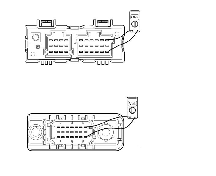
check that the CAN bus termination resistors are intact by measuring the resistance between CAN-high and CAN-low using a multimeter.
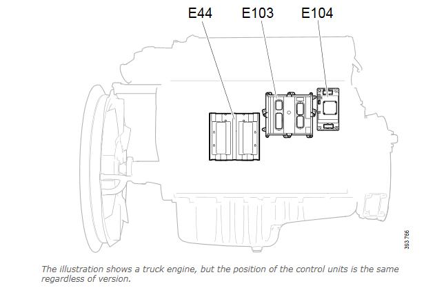
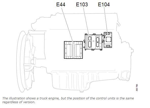
The illustration on the next page shows the junction blocks that are connected to the coordinator and the size of each termination resistor.
The measuring should be performed on the coordinator’s pin for each CAN bus with the connector connected. For example, the measuring of the green CAN bus can be performed at the coordinator’s E30.B connector between the measuring points B-3 and B-12.
Note:
To be able to measure the resistance in a CAN bus, all systems must be connected and with no power to the vehicle when measuring.
The resistance for each CAN bus must be 54-60 ohm. If the resistance is 120 ohm, this means that 1 termination resistor is missing. If the resistance is 40 or 30 ohm, then there is/are 1 or 2 termination resistors too many on the particular CAN bus. In case of too high or low resistance in the CAN bus,the next step is to measure the termination resistors for the coordinator, junction blocks and connected control units separately.
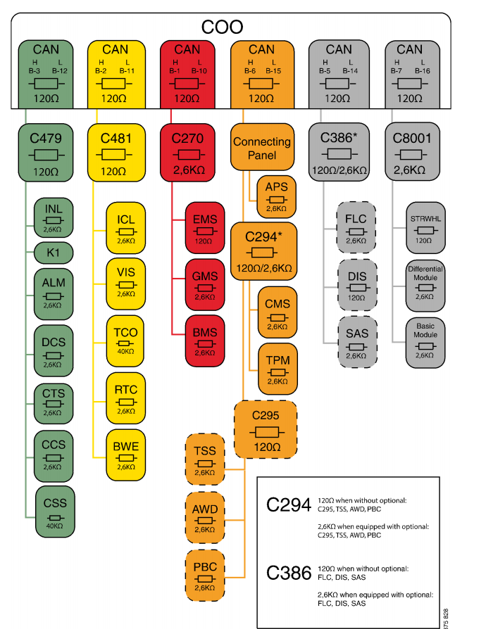
The coordinator’s and connected control units’ termination resistors are measured at the control units’ pin for each CAN bus without connectors being connected. The measured value for the coordinator should be 120 ohm. The measured values for the connected control units should be as shown in the illustration above.
The junction blocks’ termination resistors are measured on each separate junction block without connector. Check measuring of a junction block’s termination resistor is performed by measuring the upper and lower rows of pins. The middle row is used for shielding. The resistance for a separate junction block should be 120 ohm or 2.6 kohm depending on the version.
Voltage in CAN bus
It is not possible to measure the voltage in the CAN bus to see if it varies in the circuit. The multimeter only measures the average of the CAN bus’s voltage levels, but this can give sufficient information to assess the CAN bus’s electrical condition. The voltage between CAN-high and CAN-low varies the whole time depending on whether it is a 1 or 0 that is sent. When a 1 is sent, CAN-high and CAN-low are 2.5 V. When a 0 is sent, CAN H rises to approx. 4 V and CAN L drops to approx.1 V. This happens so quickly that you cannot see it on a regular multimeter. The average value shown on the multimeter should therefore be approx. 2.5 V when you measure between CAN-high and ground and CAN-low and ground. In case of too high or too low voltage in the CAN bus, the next step is to check if the CAN bus is short-circuited to the voltage supply or ground. To check if this is the case, the following measurements must be performed for the specific CAN bus. The resistance must be in the order of a megaohm and the measuring must be performed without power in the vehicle.
• Measure the resistance between CAN-high and voltage supply.
• Measure the resistance between CAN-high and ground.
• Measure the resistance between CAN-low and voltage supply.
• Measure the resistance between CAN-low and ground.
Overload in CAN bus
Faults may occur in ECU systems which make them send erroneous messages all the time in such a quantity that the communication does not work. This is called overload. Overload can cause certain messages to be forwarded and others not. Which in turn means that certain functions will fail.
If the green CAN bus is overloaded, this can also mean that SDP3 cannot be used. In case of overload on a CAN bus, one control unit at a time should be disconnected to see if the problem disappears and thereby identify the defective control unit.
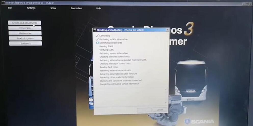
Troubleshooting: No communication between the vehicle and SDP3
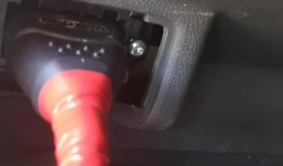
1.Check VCI – indicator lamps show status. Try to start the program again.
2.Check ICL – which systems should be there? Compare with the CAN bus chart.
3.Can ICL communicate with systems on the green CAN bus?
a) If yes, the fault is towards VCI or there is a fault in the connection to the truck or in the junction block (C479).
4.Check that the resistance on the green CAN bus between CAN-high and CAN-low is 54-60 ohm.
All systems must be connected and the vehicle without power when measuring.
a) In case of fault, check the coordinator’s, the junction block’s and connected control units’ termination resistors separately.
5.Check the voltage level for CAN-high and CAN-low in relation to the chassis ground point on the green CAN bus. The value should be approx. 2.5 V.
a) In case of fault, check the resistance between CAN-high/CAN-low and ground/voltage supply respectively. The resistance must be in the order of a megaohm or more.
– In case of fault, perform the same type of measuring on the junction block to find out in which branch of the green CAN bus there is a fault.
– Disconnect the control unit in question so that you can distinguish between faults in the control unit and faults in the cable harness. In case of fault in the cable harness – troubleshoot the
electrical cables.
6.Check that there is no overload on the green CAN bus. Disconnect one control unit at a time to see if the problem disappears and thereby identify the defective control unit.
For more information, see the Workshop Manual > 16 – 00 > Electrical system complete > CAN network.