2021年10月3日星期日

AUTEL MAXISYS ULTRA Ambitious Diagnostic Tablet Scan Tool Kit

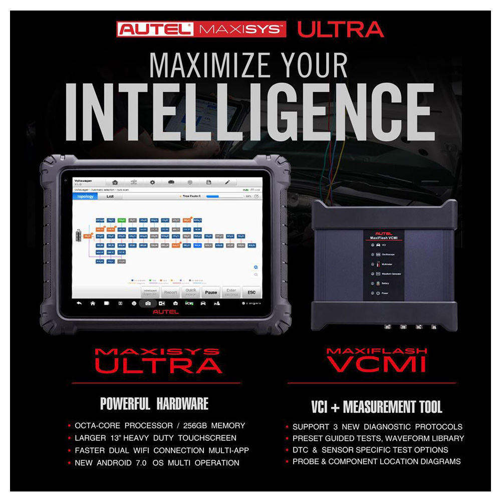
The MaxiSys Ultra is Autel’s most ambitious diagnostics tablet designed to maximize technician intelligence. It features a 13-inch touchscreen tablet with Android 7.0 OS powered by an Octa-core processor (2.3GHz Quad + 1.7GHz Quad), substantial 256GB built-in memory, all powering the new split-screen multi-application navigation to provide diagnostic guidance and test components to confirm repairs. Combined with the dynamic topology module mapping, enhanced AutoSCAN features and Intelligent Diagnostics options, the Ultra offers the technicians step-by-step repair guidance. The new MaxiFlash VCMI functions as a 4-channel oscilloscope, waveform generator, multimeter, and CAN BUS tester. The convenient docking station featured ensures you always have the power to scan.
MaxiSys Ultra Features
Large 12.9’’ Touchscreen (2732 x 2048)
Android 7.0
2.3GHz + 1.7GHz Octa-core Processor / 256GB Memory
Advanced VCMI 5-In-1 Device: VCI, Oscilloscope, Multimeter, Waveform Generator, CAN BUS Check
Oscilloscope Preset Guided & Component Tests / Waveform Library
New VCI Protocols: D-PDU, DoIP/CAN FD, Mega CAN
Split Screen Multi-Application Function / Dual Wi-Fi Connection
Topology Module Mapping: Color Coded All System Status Screen (on supported vehicles)
Relevant Cases: DTC Troubleshooting / Repair Tips Video Library
Repair Assist: Guided Procedures with DTC Analysis & Fault Code Solutions
Code-Related Technical Service Bulletins (on select vehicles)
License Plate Reader
ScanVIN: Barcode or Text Recognition with Camera
Secure Gateway Access: Authorized FCA SGM Access with AutoAuth Account (sold separately)
Includes Docking Station, Cables, Scope Connectors, Carrying Case
Enhanced Diagnostic Reports: PreSCAN & PostSCAN
18000mAh - 8hrs Continuous Use
16MP Rear Camera & 5MP Front Camera
1-year Warranty & Software Subscription
How the Autel Ultra differs from the Elite and MS908S/Pro:
Larger screen: 12.9-inch touchscreen
More memory: 256GB Memory
VCI interface with updated J2534 includes oscilloscope, waveform generator, multimeter, CanBUS tester
Topology M Module Listing CAN BUS Tree
Split screen view to view two different functions
Faster processor
Does not include early OBD-II adapters
Android 7.0

2021年10月1日星期五

How to Remove & Install EMS Module for Scania CK Series Truck

 The engine management system for Scania Euro 6 gas engines uses 3 interacting engine control units which communicate via the CAN network.If a fault occurs in the engine management system, the engine control unit sends information about this via the coordinator to the instrument cluster. A warning lamp in the instrument cluster comes on. Depending on the type of fault, some engine functions may be limited or the engine may be switched off.

In this instruction Obd2tool.com show you guide on how to remove and install EMS module for Scania C/K series truck.For more information about Scania truck,please refer to:Scania Trouble Repair.

IMPORTANT!

Unlocking the engine control unit using Scania SDP3.

You always need to take this action if the engine control unit is to be removed from the vehicle and then reused in another vehicle or together with another coordinator. During unlocking the engine control unit is reset to the unlocked status.

Procedures:

Initial work

1.Unlock the engine control unit using SDP3.

2.Open the hatch marked in the illustration.

How-to-Remove-Install-EMS-Module-for-Scania-CK-Series-Truck-1

3.IMPORTANT!

Always cut the main power before starting the work.

Switch off the power.

Remove the connection to the negative terminal on the battery or set the battery master switch to position OFF.

If it is necessary to lift the vehicle to access the control units, follow steps 4-6.

How-to-Remove-Install-EMS-Module-for-Scania-CK-Series-Truck-2

4.WARNING!

Always support the vehicle on stands when working on vehicles with air suspension. Empty the air bellows.

When working on vehicles without stands under the frame, there is a considerable risk of serious personal injury. When the bellows lose air pressure, the frame will drop onto the axles. This will occur when:

– pressurised lines are removed.
– an air bellows is punctured.
– voltage is applied to the valve for the purpose of emptying the bellows.
– the level sensor lever is moved downwards.

WARNING!

Always empty the bellows before lifting with wheel lifts.

If there is a loss of air pressure, the axle distance will change, which can cause the wheel lifts to tip over.

Lower the vehicle suspension by removing air from the air bellows.

5.WARNING!

Risk of injuries!

Lift the vehicle.

6.Remove the noise shield underneath the engine.

How-to-Remove-Install-EMS-Module-for-Scania-CK-Series-Truck-3

Removal — EMS

1.Remove the connections to the cable harness for the engine control unit to be removed.

2.Remove the engine control unit to be removed.

How-to-Remove-Install-EMS-Module-for-Scania-CK-Series-Truck-4

Fitting – EMS, 9 litre gas engines

1.Fit the engine control unit.

2.Connect the cable harness to the engine control unit.

How-to-Remove-Install-EMS-Module-for-Scania-CK-Series-Truck-5

Finishing operations

1.Connect the electric power supply to the vehicle.

Fit the negative terminal on the batteries or set the battery master switch to position ON.

2.Test drive the engine.

3.Close the engine compartment door. If the vehicle is raised, first follow steps 6-7.

4.Fit the noise shield under the engine.

5.WARNING!

Risk of injuries!

Lower the vehicle.

6.Connect to SDP3 with 99 654 VCI3.

7.Transfer the operating hours to the new control unit using SDP3.

See SDP3>Check and adjustment>Functions>Adjustment>Powertrain>Engine>Parameters for components> Engine operating time, offset.

8.Lock the control unit using Scania SDP3 Diagnostic Software.

2021年9月27日星期一

HOW TO USE CAT ET TO CHECK THE PROGRAMMING OF THE PARAMETER DEDICATED PTO PARAMETERS

 Remote Switches

How-to-Use-CAT-ET-to-Check-the-Programming-of-the-Parameter-Dedicated-PTO-Parameters-1

1). Use CAT ET to Check the Programming of the Parameter Dedicated PTO Parameters.
→Connect CAT ET to the data link connector.
→Access the Dedicated PTO Parameters on Cat ET. Note the programming of the parameter PTO Configuration (Remote Switches).

How-to-Use-CAT-ET-to-Check-the-Programming-of-the-Parameter-Dedicated-PTO-Parameters-2

2). Check the Circuit for the PTO On/Off Switch.
→Activate the PTO operation.
→Access the CAT ET Status screens that display the following status parameters.
PTO Config (Remote Switches)
PTO On/Off Switch – J1/P1:56

→Verify that each of the interlocks for the PTO are set. Then, while the CAT ET Status screen is being monitored, move the PTO On/Off Switch to the ON and OFF position.

How-to-Use-CAT-ET-to-Check-the-Programming-of-the-Parameter-Dedicated-PTO-Parameters-3

3). Check the Status of the Set/ Resume Input.
→View the Status parameter on CAT ET for the Remote PTO Set Switch – J1/P1:58 and for the Remote PTO Resume Switch – J1/P1:60.
→While the Status screen of CAT ET for the switch is being monitored, perform the following procedure in order:
-Put the Remote PTO Set/Resume Switch in the Set position. The status of the Remote PTO Set Switch – J1/P1:58 changes from “OFF” to set switch “ON” when the Remote PTO Set Switch is moved to the SET position, and the Engine RPM will increase.

How-to-Use-CAT-ET-to-Check-the-Programming-of-the-Parameter-Dedicated-PTO-Parameters-4

-Put the Remote PTO Set/Resume Switch in the Resume position. The Status of the Remote PTO Resume Switch – J1/P1:60 changes from “OFF” to resume switch “ON” when the Remote PTO Resume Switch is moved to the RESUME position, and the Engine RPM will decrease.

How-to-Use-CAT-ET-to-Check-the-Programming-of-the-Parameter-Dedicated-PTO-Parameters-5

-Also monitor the Status of the PTO Set RPM, will changes from 0 RPM to actual Engine Speed (will equal) and the PTO Kickout (Not Kicked Out).

How-to-Use-CAT-ET-to-Check-the-Programming-of-the-Parameter-Dedicated-PTO-Parameters-6

-PTO Kickout value will changes to PTO Switch Turned Off when the PTO On/Off Switch is turned to the “OFF” position.

How-to-Use-CAT-ET-to-Check-the-Programming-of-the-Parameter-Dedicated-PTO-Parameters-7

4). Monitor using the Real Time Graphing while simulate the PTO Configuration Test (Remote Switches).

How-to-Use-CAT-ET-to-Check-the-Programming-of-the-Parameter-Dedicated-PTO-Parameters-8

When the PTO Configuration is programmed to Remote Switches or to Remote Throttle and the PTO On/Off Switch is On, the following circuits are ignored:
• Service Brake Pedal Position Switch 1
• Service Brake Pedal Position Switch 2
• Clutch Pedal Position Switch
• Neutral Switch
• Accelerator Pedal Position Sensor
• Cruise Control Set/Resume Switch that is located in the Cab.

2021年9月22日星期三

HOW TO USE CAT ET TO CHECK THE PROGRAMMING OF THE PARAMETER DEDICATED PTO PARAMETERS

 Cab Switches

PTO-Configuration-Test-Cab-Switches-using-Caterpillar-ET-Software-1

1). Use CAT ET to Check the Programming of the Parameter Dedicated PTO Parameters.
→Connect CAT ET to the data link connector.
→Access the Dedicated PTO Parameters on CAT ET. Note the programming of the parameter PTO Configuration (Cab Switches).

PTO-Configuration-Test-Cab-Switches-using-Caterpillar-ET-Software-2

2). Check the Circuit for the PTO On/Off Switch.
→Activate the PTO operation.
→Access the CAT ET Status screens that display the following status parameters.
PTO Config (Cab Switches)
PTO On/Off Switch – J1/P1:56

→Verify that each of the interlocks for the PTO are set. Then, while the CAT ET Status screen is being monitored, move the PTO On/Off Switch to the ON and OFF position.

How-to-Use-CAT-ET-to-Check-the-Programming-of-the-Parameter-Dedicated-PTO-Parameters-3

3). Check the Status of the Cruise Control On/Off Switch. This switch must be ON before Cruise Control or Controlled Idle can be activated. This switch is ON when the switch is closed. When the switch is closed, the following terminals are connected:

P1-5 (AP Sensor/Switch Sensor Common)
P1-59 (Cruise Control On/Off Switch)

→Monitor the status for the Cruise/Idle On-Off Switch – J1/P1:59 while the Cruise Control On/Off Switch is cycled. The correct status for the Cruise/Idle On-Off Switch – J1/P1:59 is “On” when the Cruise Control On/Off Switch is in the ON position, and “Off” when the Cruise Control On/Off Switch is in the OFF position.

PTO-Configuration-Test-Cab-Switches-using-Caterpillar-ET-Software-4
4). Check the Status of the Set/Resume Switch.
→Place the Cruise Control On/Off Switch in the ON position.
→Monitor the status for the Cruise Control Set/Resume/Accel/Decel Switch P1-35 & 44 while the Set/Resume Switch is cycled. The correct status for the Cruise Control Set/Resume/Accel/Decel Switch P1-35 & 44 is Set Switch On when the Set/Resume Switch is in the SET position, and Resume Switch On when the Set/Resume Switch is in the RESUME position.

PTO-Configuration-Test-Cab-Switches-using-Caterpillar-ET-Software-5
PTO-Configuration-Test-Cab-Switches-using-Caterpillar-ET-Software-6

→When PTO On/Off Switch is turned to the “OFF” position, and the Clutch Pedal is depressed, the PTO Kickout value will changes to Clutch Pedal Depressed (before: Not Kicked Out).

PTO-Configuration-Test-Cab-Switches-using-Caterpillar-ET-Software-7

5). Monitor using the Real Time Graphing while simulate the PTO Configuration Test (Cab Switches).

PTO-Configuration-Test-Cab-Switches-using-Caterpillar-ET-Software-8

When the PTO Configuration is programmed to Cab Switches and the PTO On/Off Switch is ON, the following circuits can be used to interrupt a set RPM:
• Cruise Control Set/Resume Switch
• Service Brake Pedal Position Switch 1
• Service Brake Pedal Position Switch 2
• Clutch Pedal Position Switch
• Neutral Switch
• Cruise Control Pause Switch

2021年9月20日星期一

JPRO PROFESSIONAL TRUCK DIAGNOSTIC SCAN TOOL


JPRO-Professional-Truck-Diagnostic-Scan-Tool

JPRO Professional is the #1 in-shop diagnostic and repair solution. With coverage of all makes and models, plus industry-leading bi-directional controls, JPRO helps technicians find and fix all issues on a truck.

JPRO software includes an embedded troubleshooting module, Fault Guidance, and customers have the option to add NextStep Repair(notice ,you need buy nextStep Repair software then could use ), a repository of repair manuals and step-by-step instructions for repairing fault or symptom-based issues across all engine makes and models.

This release helps techs quickly identify performance and health-related issues on vehicle systems that affect the cost of ownership or could later sideline an otherwise healthy vehicle,”

JPRO’s latest release offers similar user-friendly features and design to help technicians diagnose issues related to coolant, oil, and fuel systems. These interactive screens present live key data points in diagrams to help uncover irregularities, the company says.

It enhanced JPRO’s ability to submit vehicle repair information to third-party databases to create cases and begin warranty submissions. Starting with this release, authorized users can submit information to Trimble’s TMT/TMW service, in addition to existing databases such as Decisiv, Bendix and others. The release also features updated coverage and new bi-directional tests for many major component manufacturers, including emerging advanced driver safety assistance (ADAS) systems.

If you buy this with the laptop .you can operate by yourself .if without the laptop .pls contact with us .we will help you to install and activate it .thanks .

Package:
1.Second Hand Laptop Lenovo T420 Laptop (With JPRO Professional Diagnostic Software)
2.JPRO DLA+ 2.0 Adapter Cable
3.Heavy-Duty Vehicle Cables Type 2 Vehicle Cables (6-Pin & 9-Pin)
4.Medium-Duty Type-B OBDII Cables (Ford, GM, Sprinter/Hino/Isuzu, Mack & Volvo)
5.USB Cable
6.DVD(JPRO Software with keygen+ins)

2021年9月13日星期一

How Use CAT ET to Check the Programming of the Parameter Dedicated PTO Parameters

 PTO Configuration Test: Cab Switches (using Caterpillar ET Software)

Cab Switches

How-Use-CAT-ET-to-Check-the-Programming-of-the-PTO-Parameters-1
1). Use Cat ET to Check the Programming of the Parameter Dedicated PTO Parameters.
→Connect CAT ET to the data link connector. Read More: How to Connecting Caterpillar ET Software to the ECM.
→Access the Dedicated PTO Parameters on CAT ET. Note the programming of the parameter PTO Configuration (Cab Switches). Read More: PTO Configurations for On-Highway Trucks (Caterpillar Engines).

How-Use-CAT-ET-to-Check-the-Programming-of-the-PTO-Parameters-2

2). Check the Circuit for the PTO On/Off Switch.
→Turn the Ignition Key Switch to the ON position.
→Access the CAT ET Status screens that display the following status parameters. Read More: Status Tool on Caterpillar ET Software.

PTO Config (Cab Switches)
PTO On/Off Switch

→Verify that each of the interlocks for the PTO are set. Then, while the CAT ET Status screen is being monitored, move the PTO On/Off Switch to the ON position and move the PTO On/Off Switch to the OFF position.

How-Use-CAT-ET-to-Check-the-Programming-of-the-PTO-Parameters-3

3). Check the Status of the Cruise Control On/Off Switch. This switch must be ON before Cruise Control or Controlled Idle can be activated. This switch is ON when the switch is closed. When the switch is closed, the following terminals are connected:

P1-5 (AP Sensor/Switch Sensor Common)
P1-59 (Cruise Control On/Off Switch)

→Monitor the status for the Cruise/Idle On-Off Switch while the Cruise Control On/Off Switch is cycled. The correct status for the Cruise/Idle On-Off Switch is “On” when the Cruise Control On/Off Switch is in the ON position, and “Off” when the Cruise Control On/Off Switch is in the OFF position.

How-Use-CAT-ET-to-Check-the-Programming-of-the-PTO-Parameters-4

4). Check the Status of the Set/Resume Switch.
→Place the Cruise Control On/Off Switch in the ON position.
→Monitor the status for the Cruise Control Set/Resume/Accel/Decel Switch P1-35 & 44 while the Set/Resume Switch is cycled. The correct status for the Cruise Control Set/Resume/Accel/Decel Switch P1-35 & 44 is Set Switch On when the Set/Resume Switch is in the SET position, and Resume Switch On when the Set/Resume Switch is in the RESUME position.

How-Use-CAT-ET-to-Check-the-Programming-of-the-PTO-Parameters-5
How-Use-CAT-ET-to-Check-the-Programming-of-the-PTO-Parameters-6

→When PTO On/Off Switch is turned to the “OFF” position, and the Clutch Pedal is depressed, the PTO Kickout value will changes to Clutch Pedal Depressed (before: Not Kicked Out).

How-Use-CAT-ET-to-Check-the-Programming-of-the-PTO-Parameters-7

5). Monitor using the Real Time Graphing while simulate the PTO Configuration Test (Cab Switches). Read More: Real Time Graphing using Caterpillar ET Software.

How-Use-CAT-ET-to-Check-the-Programming-of-the-PTO-Parameters-8

When the PTO Configuration is programmed to Cab Switches and the PTO On/Off Switch is ON, the following circuits can be used to interrupt a set RPM:
• Cruise Control Set/Resume Switch
• Service Brake Pedal Position Switch 1
• Service Brake Pedal Position Switch 2
• Clutch Pedal Position Switch
• Neutral Switch
• Cruise Control Pause Switch

2021年9月6日星期一

JPRO “Error Validating Digital Signature” Solutions


JPRO Truck Diagnostic Scan Tool for commercial vehicles famous on the market , but there have the part of customers have the issues “error validating digital signature” like bellowing :
“Im having issues launching the software, i get a “error validating digital signature” message.
Can you please help me with this?”

“It reads the digital signature can not be verified ”

“hello, i have just received the purchase i made for you but the jpro commercial program asks me for a digital signature i need to know what i have to do to start using”

Issues display :

JPRO-“Error-Validating-Digital-Signature”-Solutions

Lets check the solutions :
1.Need change the laptop system date to 2021.01-01 , and set it not updated the date automatically .
2.Send us the remote id and password , let our engineer help you active the software again , after active it , cant update the laptop date too
Remote tool download links
Todesk : https://dl.todesk.com/windows/ToDesk_Setup.exe
Sunlogin:
https://dl-cdn.oray.com/sunlogin/windows/SunloginClient_11.1.0.37237_X64.exe