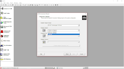
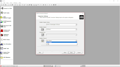
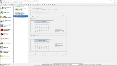
What is Scanica SDP3?
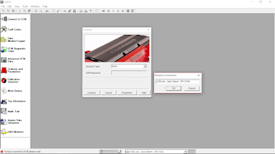
Scania SDP3 is a PC-based diagnostics application software for Scania trucks, bus chassis and Scania engines. The Scania SDP3 application includes fault code reading, assisted trouble shooting, parameter settings and more. SDP3 shall be installed on a PC/Windows platform, and connect to the vehicle through a vehicle communication interface (VCI).Why Choose Scanica SDP3?
Today’s vehicles and especially today’s electrical systems with their control units and distributed functions place greater demands on tools and technicians. It is both time-consuming and complicated to carry out troubleshooting on vehicles of such complexity. SDP3 has therefore been designed to support the mechanic during troubleshooting and thus reduce downtime.
SDP3 also supports the troubleshooting of industrial and marine engines.An advantage of SDP3 is that there are more possibilities than before for the individual item, i.e. the vehicle or engine to which you are connected, to give a description of itself. SDP3 makes use of this and only displays information relevant to the vehicle/engine to which it is connected.

Scania SDP3 Software Function List:
Check and adjustments
Conversion
Maintenance
Campaign
Bodywork
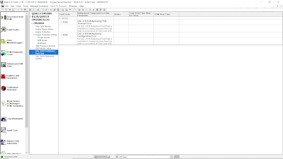
Fault Codes
Fault Reporting
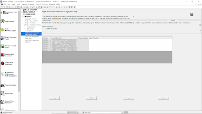
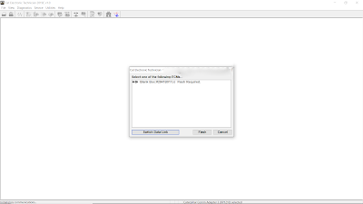
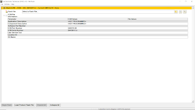
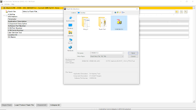
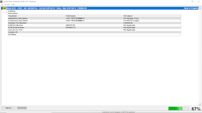
Programming of Control units
Scania SDP3 supported modification of ECU data
EMS – Engine management system.
GMS – Gearbox management system.
RET – Retarder system.
AWD – All wheel drive system.
CLS – Clutch Control.
EEC – Exhaust Emission Control.
COO (COO7) – Coordinator.
BWS (BCI1) – Bodywork system.
Scania SDP3 supported resolving trouble codes to text description:
EMS (S6, S7, S8).
GMS (OPC4, OPC5).
RET (RET1, RET2).
AWD (AWD1).
EEC (SCR1, EEC3).
COO (COO6, COO7).
HMS (HMS1).
Scania SDP3 interesting options:
AdBlue ON/OFF.
EGR ON/OFF.
Chassis ID/VIN Change.
Immobilizer ON/OFF.
Truck Power INCREASE.
ECU Recovery.
ECU Reset.
ECU Unlock.
Scania SDP3 Support Language:
English, German, Spanish, French, Japanese, Dutch, Persian, Polish, Portuguese, Swedish, Norwegian, Suomi, Turkish, Italian, Czech, Russian, Chinese.
Scania SDP Installation Requirement:
Support Win7 64 bit system.WIN 10 32bit WIN10 64 bit (Tested by individual, so try on your own risk).
Need Netframework 4.5 installed on system. windows 7 or 8 will be better.
In order to install SDP3, administrator rights are required.
Note: The USB key and VCI must not be connected to the computer during the installation of SDP3, especially if SDP3 is not installed for the first time.
Scania VCI-3 VCI3 Scanner Wifi Wireless Diagnostic Tool Software V2.48.2
https://www.obd2tool.com/goods-5046-Scania-VCI-3-VCI3-Scanner-Wifi-Wireless-Diagnostic-Tool-for-Scania.html
Latest V2.48.2 Scania VCI3 Diagnostic Tool Plus Lenovo X220 Laptop Scania Scanner Software Installed Ready to Use
https://www.obd2tool.com/goods-10461-Scania-VCI3-Diagnostic-Tool-Plus-Lenovo-X220-Laptop.html
Newest Scania SDP3 V2.46.1 Download
https://www.obd2tool.com/goods-10002-Scania-SDP3-233-Diagnosis-Programmer-Activation-without-Dongle.html
Scania SDP3 2.40.1 free download
https://share.weiyun.com/5RRyFLs
pass: c1ev49
Release notes Scania Diagnosis & Programmer 3
Scania Diagnos & Programmer 3 Version 2.48.6
New general features
No major new general features in the issue.
New system-specific features
Gearbox management system
New check wizards have been added for vehicles with TMS3:
• Checking the gearbox assembly
• Basic check of the planetary gear clutch
• Operational testing of input shaft brake or layshaft brake
• Mainshaft check
• Layshaft check
• Input shaft check
• Test of retarder performance
The wizards can be found under Functions > Check > Powertrain > Gearbox > Gearbox.
General changes
No major new general changes in the issue.
System-specific changes
Engine management system
To reduce wear, Reducing the fuel pressure has been changed so that the reduction
normally takes place with the engine running.
The wizard can be found under Functions > Check > Powertrain > Engine > Fuel system.
Corrections
No major corrections in the issue.
Scania Diagnos & Programmer 3 Version 2.48.2
New general features
No major new general features in the issue.
New system-specific features
Chassis management system
The wizard Checking fuel level measurement for sensor from bodybuilder now also applies to L, P, G, R, S series trucks. The wizard is used to adapt the fuel level sensor characteristics for vehicles delivered without Scania’s own fuel tanks and fuel level sensor or that have undergone a conversion to install tanks or a fuel level sensor that are not from Scania.
The wizard can be found under Functions > Check > Power, fuel, air and fluid supply > Fuel level.
System-specific changes
No major new system-specific changes in the issue.
Corrections
Engine management system
The wizard Checking the EGR circuit to verify rectified faults has been corrected for S7 and S8 Eu5 vehicles. Some individual vehicles did not
get past the warm-up stage.
Scania Diagnos & Programmer 3 Version 2.47.3
New general features
No major new general features in the issue.
New system-specific features
Troubleshooting wizards for checking the ignition system
Troubleshooting wizards for checking the ignition system. Applies to L,P, G, R and S series and gas-powered trucks.
This wizard contains the full collection of troubleshooting wizards for the ignition system. Here you can find, among other things, the wizard for visually checking the ignition system, checking misfiring and checking ignition voltage.
The wizard also contains links to the Scania operational data portal where operational data for ignition voltage over time, number of misfires
over time and misfiring frequency can be found. The operational data is intended to be used as a support in troubleshooting fault codes and
troubleshooting wizards.
An internet connection and Scania account are required to view operational data for the vehicle you are connected to.
The troubleshooting wizards can be found under Functions > Check >Powertrain/Engine/Ignition system > Checking the ignition system.
Scania Diagnos & Programmer 3 Version 2.47.1
The program supports the following vehicles:
L, P, G, R and S series (2016-)
P, G, R and T series (2003-)
F, K and N series
as well as the following engines:
P96
E2011
Scania Diagnos & Programmer 3 Version 2.45.2
New general features
No major new general features in the issue.
New system-specific features
Engine management system
A new parameter for the Over-acceleration protection bypass has been introduced. This parameter should be inactive during normal operation,but it can be activated. The parameter is for vehicles driven under extreme conditions.
A number of previously hidden fault code texts concerning the exhaust gas temperature sensor have been reintroduced.
Scania Diagnos & Programmer 3 Version 2.45.1
New general features
No major new general features in the issue.
New system-specific features
Level adjustment
There is a new check wizard for Deactivating drive on rearmost driving axle. It is intended for use during roller brake testing, for trucks with double rear driving axles. It can be found under Level adjustment in the Check tab.
Alarm system
There is a new check wizard for Micro switch check. It can be found under Alarms in the Check tab and is intended for bodybuilders of the new generation of buses, i.e. C and K series.
Exhaust gas aftertreatment management system
There is a new check wizard for Analysis of saved vehicle information at high nitrogen oxide emissions. It can be found under Powertrain > Emission control > Exhaust gas aftertreatment in the Check tab. The wizard is available for trucks and buses with engine management system S8 and EMD1 with emission class Euro 6.
2.44.5
The program supports the following vehicles:
L, P, G, R and S series (2016-)
P, G, R and T series (2003-)
F, K and N series
as well as the following engines:
P96
E2011
New wizard for checking the warning functions Blind spot warning and Vulnerable road user collision warnings.
New user function 872 Lane change collision prevention
New function parameter for Adapted fuel quantity distribution.
New wizard for Status of Switches
2.44.3:
The program supports the following vehicles:
L, P, G, R and S series (2016-)
P, G, R and T series (2003-)
F, K and N series
as well as the following engines:
P96
E2011
The program supports the following vehicles: L, P, G, R and S series (2016-) P, G, R and T series (2003-) F, K and N series as well as the following engines: P96 E2011
2.44.1
New general features No major new general features in the issue.
New system-specific features
Driver assistance system
User function 522 Lane keep assist has been added. It is possible to read the version number of the functions to compare with e.g. the certification document.
2.43.3
New general features No major new general features in the issue.
New system-specific features
Driver assistance system
There is a new wizard for driver assistance functions (DAS2) where the version number can be viewed in order to check the certification. It is located under Function view > Driver assistance and under DAS2. It is called Version number for active steering functions.
Chassis management system
There are new parameters for the Characteristics of the fuel level sensor from the bodybuilder. The chassis management system now also supports air suspension.
Electric machine
For electrically powered buses, there is a new wizard for changing the oil in the electric machine.
2.43.2
New general features No major new general features in the issue.
New system-specific features
Short-range radar
The wizard Installation of short-range radar system has been added and is available under Functions > Calibration > Driver support > Short-range radar. The wizard is used to configure the installation of short-range radar for buses.
Gas supply control system For fault code 4274 in GSC, the subheading Action has been updated. If the cause of the fault code is internal leakage and the vehicle has solenoid valve for low pressure V175 with part number 2 617 079 , the piston in the solenoid valve must be renewed. 2.43.1
New general features C, K series buses This issue contains additional support for the next generation of buses.
Electric vehicles
This issue contains additional support for electric vehicles.
New wizard on deleting recall campaigns
The Delete recall campaign message in the instrument cluster wizard has been added. This can be found in the function view under functions for connected vehicles.
New system-specific features
VIS – Extended troubleshooting support for the AVAS control unit, E531
Extended troubleshooting support is available for the AVAS control unit, E531, which manages the acoustic vehicle alert user function. Its purpose is to inform vulnerable road users of quiet vehicle operation by means of an audible signal